Power transmitting apparatus, power receiving apparatus, and power transmitting method

A technology of power receiving device and power transmission unit, which is applied in the direction of circuit devices, circuit certification, electrical components, etc., and can solve problems such as short distances

Inactive Publication Date: 2013-10-09
PANASONIC CORP
View PDF5 Cites 46 Cited by
  • Summary
  • Abstract
  • Description
  • Claims
  • Application Information

AI Technical Summary

Problems solved by technology

Generally speaking, the transmission distance of the electromagnetic induction method is short

Method used


Image

  • Power transmitting apparatus, power receiving apparatus, and power transmitting method
  • Power transmitting apparatus, power receiving apparatus, and power transmitting method
  • Power transmitting apparatus, power receiving apparatus, and power transmitting method

Examples


Embodiment approach

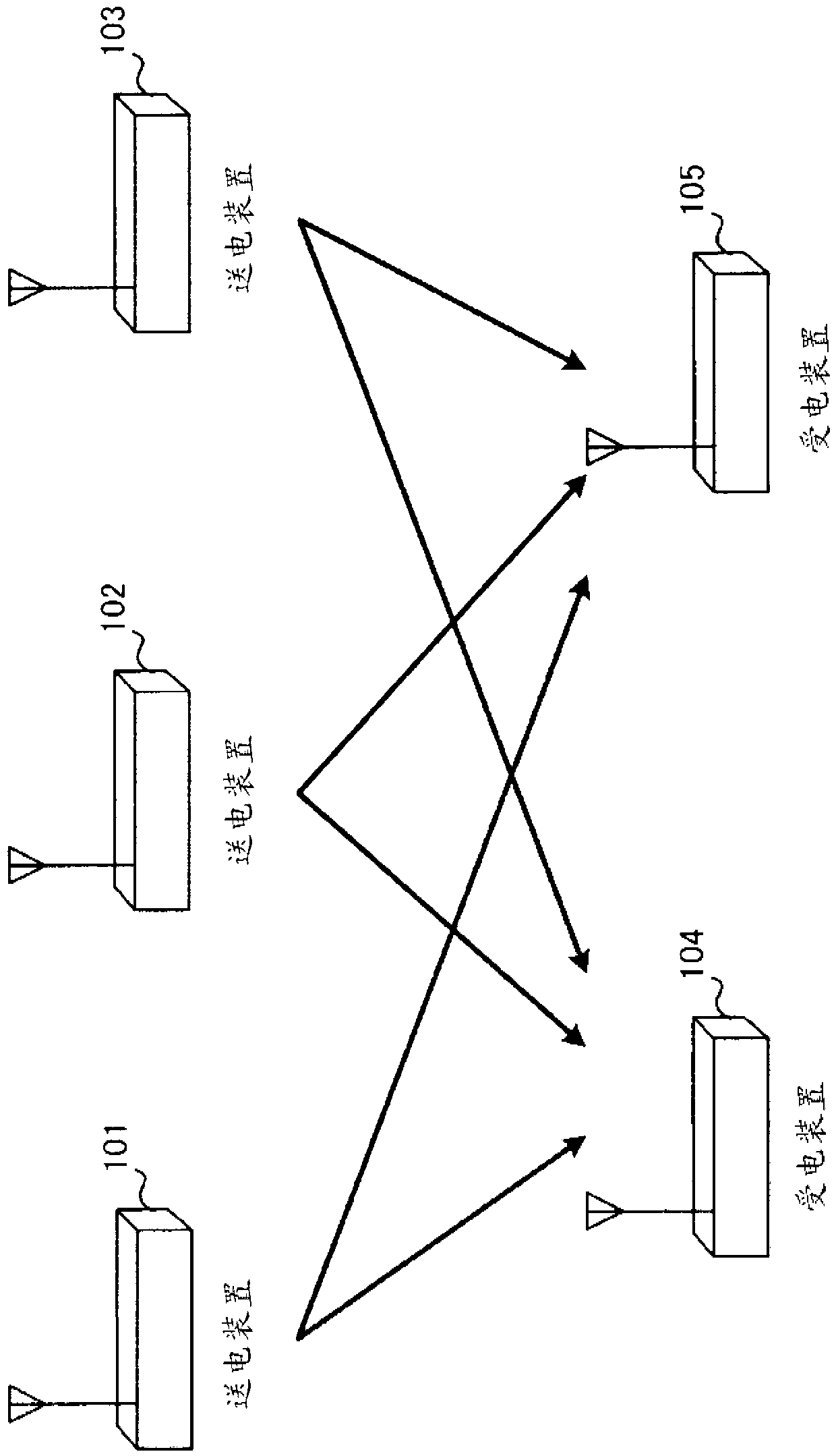
[0058] figure 1 It is a figure which shows the outline|summary of the wireless power transmission system in embodiment of this invention.

[0059] figure 1 The wireless power transmission system in the above is, for example, an example in which the plurality of power transmitting devices 101 to 103 and the power receiving devices 104 and 105 mainly use magnetic resonance of the same frequency as the frequency of power transmission to realize wireless power transmission. in addition, figure 1 The wireless power transmission system has 3 power transmitting devices and 2 power receiving devices, but the number of power transmitting devices and power transmitting devices that the wireless power transmission system has is not limited thereto.

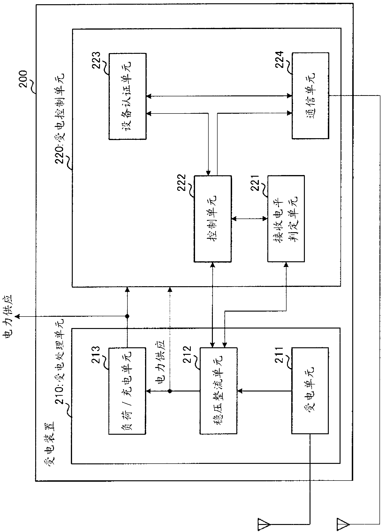
[0060] figure 2 It is a block diagram showing an example configuration of the power receiving device of the present embodiment. figure 2 The powered device 200 is suitable for figure 1 The power receiving devices 104, 105.

[0061] e...


PUM


Abstract

Provided is a power transmitting apparatus, which can start power transmission even in the cases where there is not even residual power with which a power receiving apparatus requests power transmission, in a wireless power transmission system, in which a plurality of power transmitting apparatuses and a plurality of power receiving apparatuses are mainly using a same frequency as a power transmission frequency. A power transmitting apparatus (300) has sub-power transmission mode, and main power transmission mode for transmitting power larger than that transmitted in the sub-power transmission mode. A power transmitting unit (310) transmits power in a wireless manner. A power transmission control unit (320) controls, in sub-power transmission mode, power to be transmitted by means of the power transmitting unit (310) and transmission timing of the power transmission such that at least power that the receiving apparatus needs to transmit power request notification is transmitted at random intervals. A power transmission control unit (320) performs switching to the main power transmission mode, in the cases where a communication unit (350) acquired the power request notification transmitted from the power receiving apparatus.

Description

technical field [0001] The present invention relates to a power transmission device, a power reception device and a power transmission method for non-contact power transmission. Background technique [0002] In recent years, non-contact power transmission technology has been widely used in IC (Integrated Circuit, integrated circuit) cards, electronic money systems, and the like. [0003] In addition, compared with non-contact power transmission technology, it is also actively researching wireless power transmission methods that can realize long-distance transmission. Broadly speaking, there are three types of wireless power transmission methods, that is, a method using electromagnetic induction (electromagnetic induction method), a method using radio waves (radio wave transmission method), and a method using magnetic resonance (magnetic resonance method). [0004] The electromagnetic induction method uses two coils to transmit electric power by utilizing the induced current...

Claims


Application Information

Patent Timeline
Patent Type & Authority Applications(China)
IPC IPC(8): H02J17/00
CPCH04B10/807H02J5/005H04B3/00H02J17/00H04B5/0037H04B5/0081H02J50/12H02J7/0068H02J7/00045H02J50/80H02J50/40
Inventor 竹内一真
Owner PANASONIC CORP
Why Eureka
Try Eureka