Frequency translation filter apparatus and method

A frequency conversion and filter technology, applied in the field of frequency conversion filter equipment, can solve problems such as complex costs

Active Publication Date: 2013-10-09
TELEFON AB LM ERICSSON (PUBL)
View PDF3 Cites 4 Cited by
  • Summary
  • Abstract
  • Description
  • Claims
  • Application Information

AI Technical Summary

Problems solved by technology

[0009] therefore, Figure 4 The circuit arrangement of is a complicated and costly way to handle multiple received carriers with non-contiguous frequencies

Method used


Image

  • Frequency translation filter apparatus and method
  • Frequency translation filter apparatus and method
  • Frequency translation filter apparatus and method

Examples


Embodiment Construction

[0036] The following embodiments will be described with respect to having first and second aggregated carriers in the received signal. Note, however, that the present invention is intended to cover any number of multiple carriers in a received signal. Furthermore, the present invention can also be used to receive multiple non-contiguous frequency ranges.

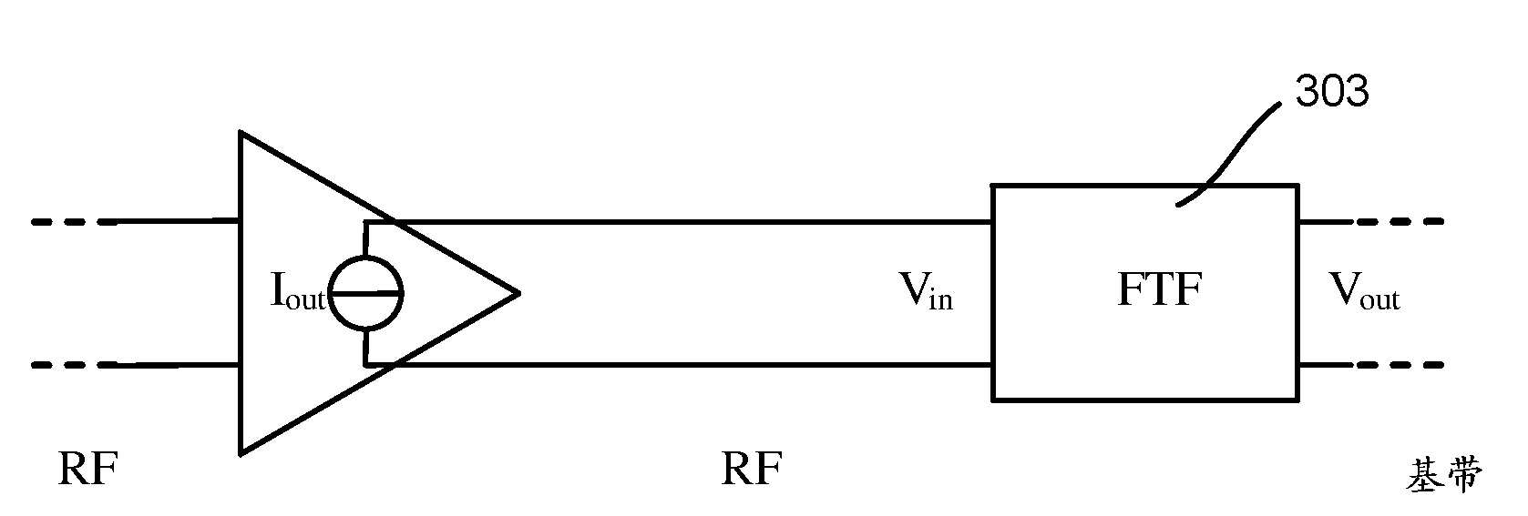
[0037] Figure 5a A frequency conversion filter 500 according to one embodiment of the invention is shown. The frequency conversion filter 500 is configured to receive a radio frequency (RF) signal 501 comprising first and second non-contiguous carriers or non-contiguous frequency ranges. The frequency conversion filter includes a mixer 503 (eg, a passive mixer) configured to combine an RF signal 501 received on a first input with a local oscillator signal (LO_RF) received on a second input 505 for mixing. Filter 507 includes a frequency dependent load impedance whereby filter 507 has a frequency conversion that includes...


PUM


Abstract

A frequency translation filter 500 is configured to receive a radio frequency (RF) signal 501 comprising first and second non-contiguous carriers or non-contiguous frequency ranges. The frequency translation filter comprises a mixer 503 configured to mix the RF signal 501 received on a first input with a local oscillator (LO) signal 505 received on a second input. A filter 507 has band-pass characteristics which, when frequency translated using the mixer 503, contain first and second pass-bands corresponding to the first and second non-contiguous carriers or non-contiguous frequency ranges. The first and second pass-bands are centered about the local oscillator frequency.

Description

technical field [0001] The present invention relates to a frequency translation filter arrangement and method, in particular to a frequency translation filter arrangement and method for handling carrier aggregation in a radio receiver. Background technique [0002] Radio frequency receivers have traditionally used filters such as Surface Acoustic Wave (SAW) or Bulk Acoustic Wave (BAW) filters. However, in order to reduce the component size and power consumption of filters used in such radio receivers, and to make such filters more compatible with integrated process technologies such as CMOS fabrication, frequency conversion filter technology has been developed. [0003] figure 1 The basic structure of the frequency conversion filter is shown. including switching element 101 a to 101 d A passive mixer 101 is used to frequency convert a frequency dependent impedance in the form of a capacitor 103 . The operation of the mixer 101 can be viewed as using a local oscillator (...

Claims


Application Information

Patent Timeline
Patent Type & Authority Applications(China)
IPC IPC(8): H03D7/16
CPCH03D7/166H03H19/002H03D7/16
Inventor S.马特蒂森L.森德斯特雷姆
Owner TELEFON AB LM ERICSSON (PUBL)
Why Eureka
Try Eureka