A telescopic structural unit and a telescopic rod composed of the structural unit

A telescopic structure and telescopic rod technology, applied in the direction of fluid pressure actuating device, etc., can solve the problems of complicated operation, explosive cylinder, high safety, etc., and achieve the effect of simple operation, low safety hazard, and reduced safety hazard.

Active Publication Date: 2015-12-09
江苏商舟智能装备研究院有限公司
View PDF7 Cites 0 Cited by
  • Summary
  • Abstract
  • Description
  • Claims
  • Application Information

AI Technical Summary

Problems solved by technology

[0002] In the current technology, the telescopic rod-shaped structure can be embodied as a gas spring, such as the gas spring disclosed in the invention patent application with the application publication number CN101696717A, which includes a piston rod connected to the inner tube, and one end of the inner tube is provided with button, the front end of the piston rod is provided with a sealing rubber ring, the piston rod is provided with a rear collar and a bowl-shaped pad, and the rear end of the piston rod is provided with a sealing rubber ring and an air hole: the inner tube is provided with a support rod to support There are fasteners on the rod, a start switch on the support rod, a control valve on the start switch, and a sealing rubber ring on the control valve; this kind of gas spring structure is filled with high-pressure gas inside, which is easy to use during use. Cylinder explosion, a high safety hazard
[0003] This telescopic rod-shaped structure can also be embodied as a hydraulic support, such as a three-telescopic column and a hydraulic support disclosed in the invention patent application with the application publication number CN101845957A. The three telescopic columns include an outer cylinder body, an outer cylinder body There is a first-level middle cylinder inside, a second-level middle cylinder is arranged inside the first-level middle cylinder, and a live column is arranged inside the second-level middle cylinder; the upper chamber oil port and the lower chamber oil port are arranged on the outer cylinder body; the first-level middle cylinder has a The bottom wall is provided with a first bottom valve, and the bottom wall of the first-stage middle cylinder is provided with a first bottom valve; the side wall of the first-stage middle cylinder is provided so that the upper chamber of the outer cylinder body and the upper chamber of the first-stage middle cylinder The first oil hole connected to each other; the side wall of the first-stage middle cylinder is provided with the first oil hole that connects the upper chamber of the first-stage middle cylinder with the upper chamber of the first-stage middle cylinder; this kind of hydraulic telescopic structure requires external hydraulic A power source such as a pump realizes the liquid flow between the oil ports of the upper and lower chambers, and makes the hydraulic pressure in the cylinder reach a certain level, so as to realize the telescopic function; this kind of telescopic method requires the help of external force, and the operation is more complicated

Method used


Image

  • A telescopic structural unit and a telescopic rod composed of the structural unit
  • A telescopic structural unit and a telescopic rod composed of the structural unit
  • A telescopic structural unit and a telescopic rod composed of the structural unit

Examples


Embodiment 1

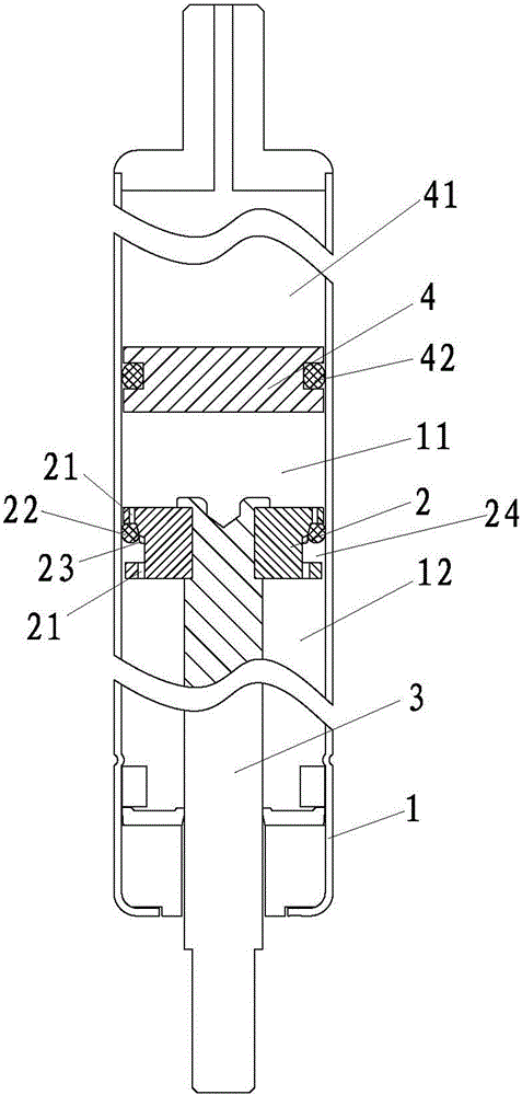
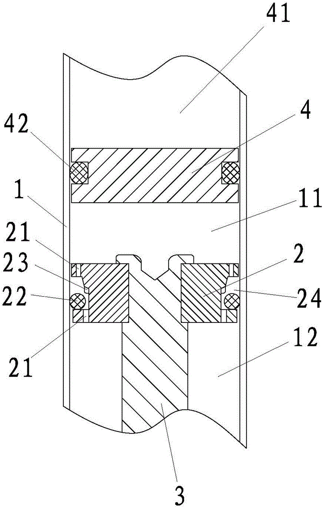
[0036]Embodiment 1: A telescopic structural unit that enables the piston rod to be relatively fixed relative to the cylinder in the original moving direction of the piston rod by increasing the pulling force or increasing the pulling speed, such as Figure 1-3 As shown, including the cylinder body 1, the cylinder body 1 is provided with a floating piston 4 that is sealed and slidably connected with the inner wall of the cylinder body 1 through the first sealing ring 42, and the floating piston 4 divides the cylinder body 1 into an exhaust chamber 41 that communicates with the atmosphere and A liquid chamber that is sealed and filled with liquid. The valve body 2 is arranged in the liquid chamber. The valve body 2 divides the liquid chamber into a liquid chamber 11 and a liquid chamber 2 12, and the liquid chamber 11 is located between the liquid chamber 12 and the exhaust chamber 41 between; the valve body 2 is fixed with a piston rod 3, and the piston rod 3 extends to the outs...

Embodiment 2

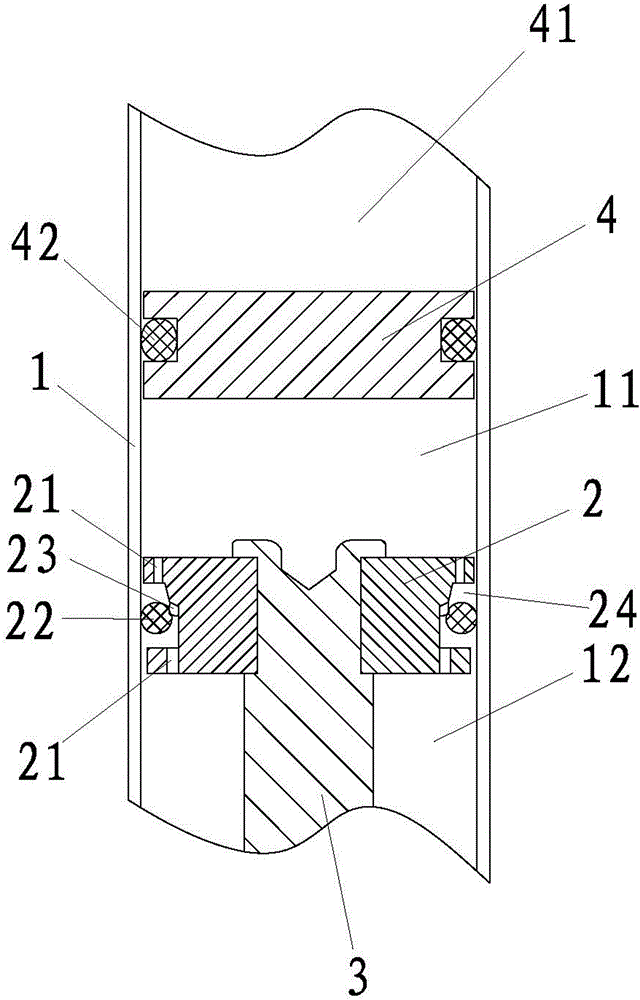
[0042] Embodiment 2: The difference with Embodiment 1 is that, as Figure 4 As shown, the resistance member 23 is a step that reflects the change of the outer diameter of the inner wall of the flow chamber 24. In order to facilitate the flow of the liquid in the first liquid chamber 11 and the second liquid chamber 12 when the sealing member 22 is in contact with the resistance member 23, at the step There should be a groove for easy circulation, the groove is not shown in the figure.

Embodiment 3

[0043] Embodiment 3: The difference with Embodiment 1 is that, as Figure 5 As shown, the channel 21 communicates with two openings of the flow chamber 24 , wherein the opening closer to the second liquid chamber 12 is disposed on the inner side wall of the flow chamber 24 .

[0044] As an option, the channel 21 communicates with the two openings of the flow chamber 24, and the opening closer to the liquid chamber 11 can also be arranged on the inner side wall of the flow chamber 24, as long as the opening can be closed by the sealing member 22. For this purpose, the position change of this opening is not shown in the figure.


PUM


Abstract

The invention relates to a telescopic structure unit and a telescopic rod composed of the telescopic structure unit. According to the technical scheme, the telescopic structure unit comprises a cylinder body, a valve body, a piston rod, a channel, a sealing body and a resistance part. The channel passes through the valve body, liquid can flow through the channel, the sealing body can seal the channel, and when the sealing body generates the trend of sealing the channel and has the trend of moving toward the corresponding direction, the resistance part can provide resistance for the sealing body. The cylinder body is filled with liquid, the potential safety hazards brought by high-pressure gas in the prior art are avoided, moreover, the extending-retracting operation can be achieved through manual drawing or compressing, and the telescopic structure unit is easy and convenient to operate and can suspend continuous relative displacement of the piston rod and the cylinder body in one direction through master of operating force.

Description

technical field [0001] The invention relates to a telescopic structure unit and a telescopic rod composed of the structure unit. Background technique [0002] In the current technology, the telescopic rod-shaped structure can be embodied as a gas spring, such as the gas spring disclosed in the invention patent application with the application publication number CN101696717A, which includes a piston rod connected to the inner tube, and one end of the inner tube is provided with button, the front end of the piston rod is provided with a sealing rubber ring, the piston rod is provided with a rear collar and a bowl-shaped pad, and the rear end of the piston rod is provided with a sealing rubber ring and an air hole: the inner tube is provided with a support rod to support There are fasteners on the rod, a start switch on the support rod, a control valve on the start switch, and a sealing rubber ring on the control valve; this kind of gas spring structure is filled with high-pres...

Claims


Application Information

Patent Timeline
Patent Type & Authority Patents(China)
IPC IPC(8): F15B15/16
Inventor 吕国祥王仁杰
Owner 江苏商舟智能装备研究院有限公司
Why Eureka
Try Eureka