Multifunctional magnetic valve lock

A multi-function, magnetic lock technology, applied in valve details, valve devices, engine components, etc., can solve the problems of high manufacturing cost of magnetic opening keys, limited application of magnetic locking valves, troublesome maintenance and repair work, etc., to prevent malicious The effect of using water and gas energy in arrears, saving management time and management costs, and protecting legitimate interests

Active Publication Date: 2015-09-23
SHANGHAI HUHANG VALVE CO LTD
View PDF6 Cites 0 Cited by
  • Summary
  • Abstract
  • Description
  • Claims
  • Application Information

AI Technical Summary

Problems solved by technology

Although this magnetic encryption method is simple and convenient, it must be opened or closed with the help of a magnetic key to open or close the valve, and its use is limited. Due to the high manufacturing cost of the magnetic key, generally many magnetic lock ball valves are equipped. A magnetic key, and the pipeline is generally in normal use, and there are still a few cases of malicious arrears. During most of the normal use of the pipeline, once the pipeline is damaged, the magnetic locking valve cannot be closed in time. On the one hand, there will be waste of water or air, on the other hand, it will bring trouble to maintenance and repair work
[0003] In addition, because the top of the upper bonnet 3' can still be clamped by common opening tools, when the magnetic lock is used in public places, when the magnetic opening key is not working and is put away, people will mistakenly think that the magnetic encryption valve is not Ordinary magnetic valves are valves that can be unscrewed by ordinary opening tools. When the valve is improperly opened or illegally opened, since the upper bonnet is fixed on the bonnet, it cannot be rotated with ordinary opening tools. Damaged due to improper opening of people, the phenomenon that the magnetic encryption valve in the pipeline is illegally opened and damaged often occurs. This phenomenon limits the application of magnetic locking valves in public places and greatly reduces the application range of magnetic locking valves.

Method used


Image

  • Multifunctional magnetic valve lock
  • Multifunctional magnetic valve lock
  • Multifunctional magnetic valve lock

Examples


Embodiment Construction

[0023] The present invention will be further described in conjunction with the accompanying drawings and specific embodiments.

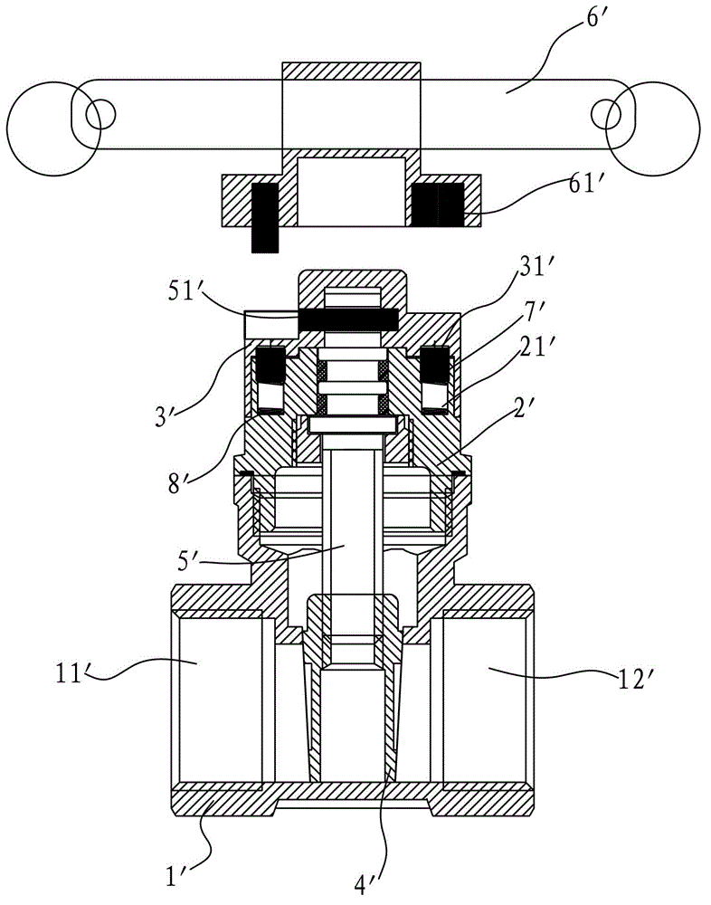
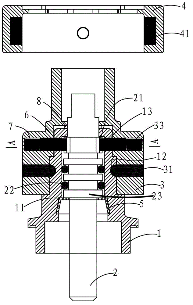
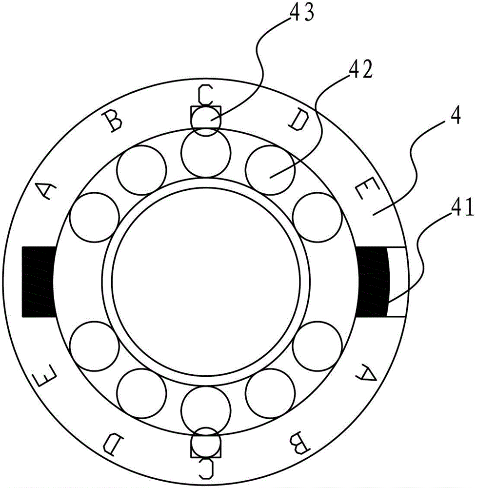
[0024] refer to Figure 2 to Figure 4, This embodiment discloses a multifunctional magnetic valve lock, which is arranged on the upper part of the valve body of the valve to control the opening and closing of the valve core. The magnetic valve lock includes a valve cover 1, a valve stem 2, a magnetic lock sleeve 3 and Magnetic unlocking cover 4, the valve cover 1 is arranged on the upper part of the valve body of the valve, the valve stem 2 is rotatably arranged on the valve cover 1 for controlling the opening and closing of the valve core, the valve stem 2 and the valve cover 1 There is an axial limit device that restricts the axial movement of the valve stem 2 when it rotates. The axial limit device includes a limit clip 5, and the inner wall of the lower part of the valve cover 1 is provided with a limit clip. 5, the circlip groove 11, the limit ...


PUM


Abstract

The invention relates to a flow control valve, and provides a multifunctional magnetic valve lock. The multifunctional magnetic valve lock is arranged on the upper portion of a valve body of a valve and used for controlling opening and closing of a valve core, and comprises a valve cover, a valve rod, a magnetic locking sleeve and a magnetic unlocking cover, wherein the valve cover is arranged on the upper portion of the valve body of the valve, the valve rod is arranged on the valve cover in a rotatable mode and used for controlling opening and closing of the valve core, an axial limiting device for limiting the valve rod to do axial movement in rotation is arranged between the valve rod and the valve cover, the magnetic locking sleeve is sleeved on the upper portion of the valve cover in a rotatable mode and connected with the valve cover in a rotatable mode through an idling bearing pin into a whole, a magnetic locking structure capable of limiting the valve rod and the magnetic locking sleeve to do circumferential rotation is arranged between the magnetic locking sleeve and the valve cover, the magnetic unlocking cover is sleeved on the upper portion of the magnetic locking sleeve in an extracting and inserting mode and used for removing the magnetic locking structure of the magnetic locking sleeve to enable the magnetic locking sleeve to be capable of doing circumferential idling movement around the valve cover and to enable the valve rod to be capable of screwing open along with a common opening key, and a circumferential limiting device is arranged between the magnetic unlocking cover and the magnetic locking sleeve.

Description

technical field [0001] The invention relates to a control part of a fluid valve, in particular to a multifunctional magnetic valve lock. Background technique [0002] Such as figure 1 , a traditional magnetic locking valve, including a valve body 1', a valve cover 2', an opening and closing member 4', a valve stem 5' and an opening key 6', the valve cover 2' is set above the valve body 1', the The valve body 1' is provided with a fluid channel through the medium along the axial part. The fluid channel has a water inlet 11' and a water outlet 12'. Between the water inlet 11' and the water outlet 12', one end of the valve rod 5' is threaded through the valve cover 2' and the opening and closing member 4', and the valve cover 2' is also provided with a limit valve The magnetic locking mechanism that the rod 5' rotates, the unlocking key 6' is provided with an unlocking mechanism for releasing the magnetic locking mechanism, the magnetic locking mechanism includes an upper val...

Claims


Application Information

Patent Timeline
Patent Type & Authority Patents(China)
IPC IPC(8): F16K35/16
Inventor 陈世伟陈建华郑盛丰郑开省史双田陈文恭
Owner SHANGHAI HUHANG VALVE CO LTD
Why Eureka
Try Eureka