Imaging and temperature measuring device for bogie and underframe of running train

A bogie and vehicle technology, which is applied in transportation and packaging, railway vehicle shape measuring devices, railway car body parts, etc., can solve the problems of train operation safety hazards, failure to alarm, high false alarm rate, etc., and achieve accurate axle temperature alarm rate The effects of improving performance, avoiding economic losses, and eliminating potential safety hazards

Active Publication Date: 2013-10-23
CHENGDU KNIGHT TECH +1
View PDF6 Cites 6 Cited by
  • Summary
  • Abstract
  • Description
  • Claims
  • Application Information

AI Technical Summary

Problems solved by technology

The existing problems are: 1. It can only detect the local temperature value in the point-type scanning area inside and outside the bearing. When high-temperature foreign objects generated by factors such as train brakes fall into the local area scanned by the sensor, false alarms will occur. 2. Since the train moves in a serpentine shape, its shaking rate is about ±30 mm, and due to the flat wheel phenomenon of the wheels and For reasons such as scratches on the rail surface, the train vehicle often jumps up and down during operation. It is difficult for the sensor to align with the same position of the bearing. It is inevitable that there will be missed detection and wrong detection, and the detected temperature value is not accurate. , Poor reliability; the accuracy rate of the alarm is only about 70%, which cannot guarantee the safe and reliable operation of the train
3. It can only detect the local temperature of the bearing, but not the temperature of the entire bearing and the wheel. When the abnormal temperature of the wheel and other parts of the bearing may cause a train accident, it cannot call the police, resulting in serious hidden dangers to the safety of train operation.

Method used


Image

  • Imaging and temperature measuring device for bogie and underframe of running train

Examples


Embodiment

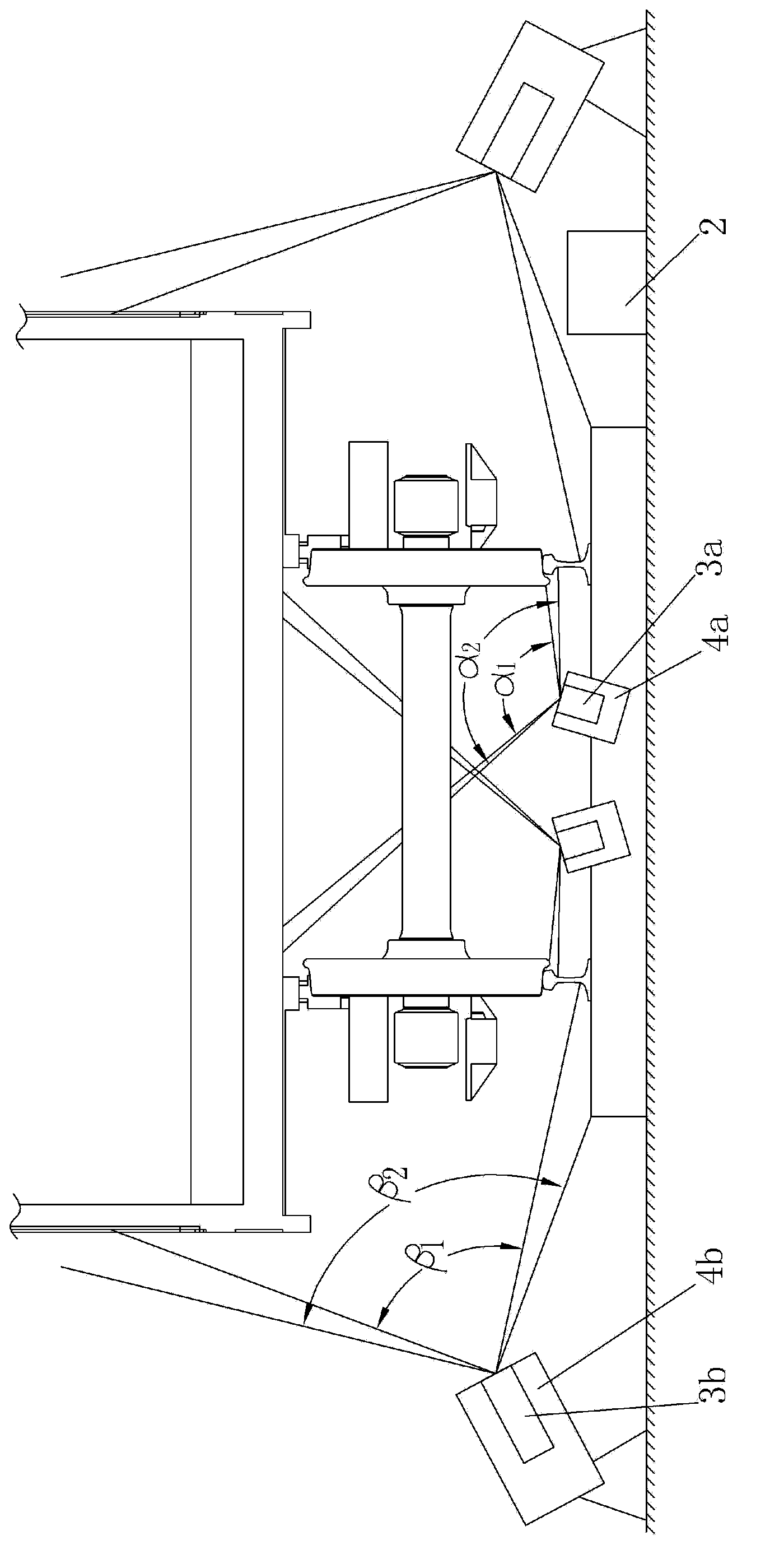
[0017] figure 1 It is shown that a specific embodiment of the present invention is a bogie and underframe imaging and temperature measuring device for running trains, which consists of two orbital center array focal plane infrared thermal imaging sensors 3a installed on the orbital center , a trackside array focal plane infrared thermal imaging sensor 3b is installed on both sides of the track; two track center visible light imagers 4a are installed on the track center, and a track side visible light imager 4b is installed on both sides of the track;

[0018] The track center array focal plane infrared thermal imaging sensor 3a, the track side array focal plane infrared thermal imaging sensor 3b, the track center visible light imager 4a and the track side visible light imager 4b are all connected to the industrial computer 2 on the track side.

[0019] In this example, the superposition of the field of view α1 of the two orbital center array focal plane infrared thermal imagin...


PUM


Abstract

An imaging and temperature measuring device for a bogie and an underframe of a running train comprises one or more than one rail core array-type focal plane infrared thermal imaging sensor mounted on a rail core, and one or more than one rail core visible light imaging device mounted on the rail core, wherein two rail side array-type focal plane infrared thermal imaging sensors are respectively mounted on two sides of a rail; two rail side visible light imaging devices are respectively mounted on two sides of the rail; the rail core array-type focal plane infrared thermal imaging sensors, the rail side array-type focal plane infrared thermal imaging sensors, and the rail core visible light imaging devices and the rail side visible light imaging devices are all connected with an industrial personal computer on the rail edge. The imaging and temperature measuring device can measure the temperature data of the whole bogie, including bearings and wheels, and distribution of the temperature data, and the temperature measurement can achieve alarm in case of not only axle temperature distribution abnormality but also wheel temperature distribution abnormality and simultaneously can accurately discover whether members of the underframe drop off or are damaged, so that the alarm accuracy is remarkably improved, and the running safety of the train is comprehensively and reliably ensured.

Description

technical field [0001] The invention relates to an imaging and temperature measuring device for a running train vehicle bogie and an underframe. Background technique [0002] The present invention is related to the infrared shaft temperature detection system (THDS) in the 5T system of the railway vehicle safety monitoring system. The infrared shaft temperature detection system is to ensure the safety of railway transportation and prevent the possible occurrence of freight train vehicles during operation. Due to the abnormal rise in the temperature of the vehicle bearings, the overheated bearing will break, that is, the so-called serious driving safety accident of the vehicle eagerly cutting the shaft. Important driving safety accidents Security monitoring facilities. [0003] The infrared shaft temperature detection system (THDS) has been gradually promoted in my country's railway vehicle safety monitoring system in the 1970s and has a history of more than 40 years. The sy...

Claims


Application Information

Patent Timeline
Patent Type & Authority Applications(China)
IPC IPC(8): B61K9/04B61K9/00
Inventor 陈子康
Owner CHENGDU KNIGHT TECH
Why Eureka
Try Eureka