
Self-adjusting thread tensioning device for winding yarns

A technology of tensioning device and winding machine, which is applied in the direction of transportation and packaging, conveying filamentous materials, thin material processing, etc., and can solve problems such as tension cannot be adjusted and problems in use

Active Publication Date: 2013-10-23
SAVIO MACCHINE TESSILI
View PDF16 Cites 5 Cited by
  • Summary
  • Abstract
  • Description
  • Claims
  • Application Information

AI Technical Summary

Problems solved by technology

In this type of line tensioner, once the weight and relay have been selected and installed, the configuration of the line tensioner and the tension applied to the line cannot be adjusted in any way
In utility models JP5117547 and JP5130235, the diverter elements include eyelets in which the wire is slotted, which makes the use of these diverter elements in normal automatic winding machines problematic

Method used


Image

  • Self-adjusting thread tensioning device for winding yarns
  • Self-adjusting thread tensioning device for winding yarns
  • Self-adjusting thread tensioning device for winding yarns

Examples


Embodiment Construction

[0029] by pair Figures 1 to 4 The features and advantages of the line tensioning device according to the invention will become clearer from the description of typical embodiments of the invention shown in the description, which are given as examples and not for purposes of limitation.

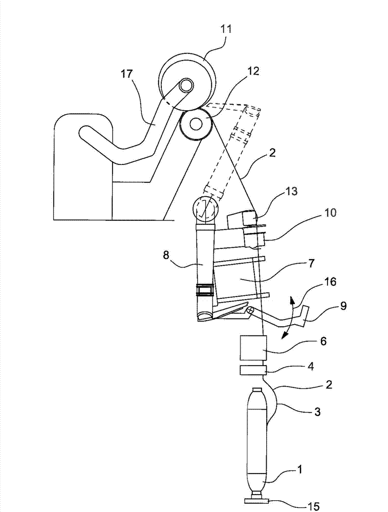
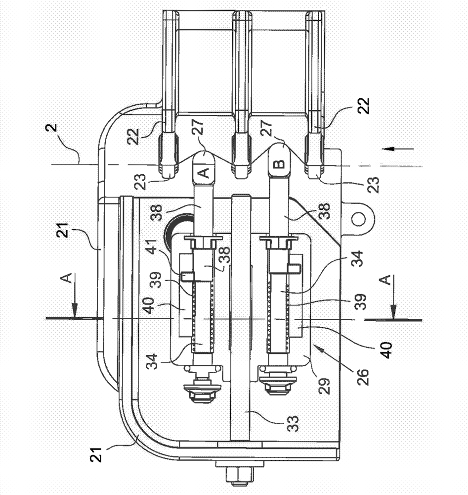
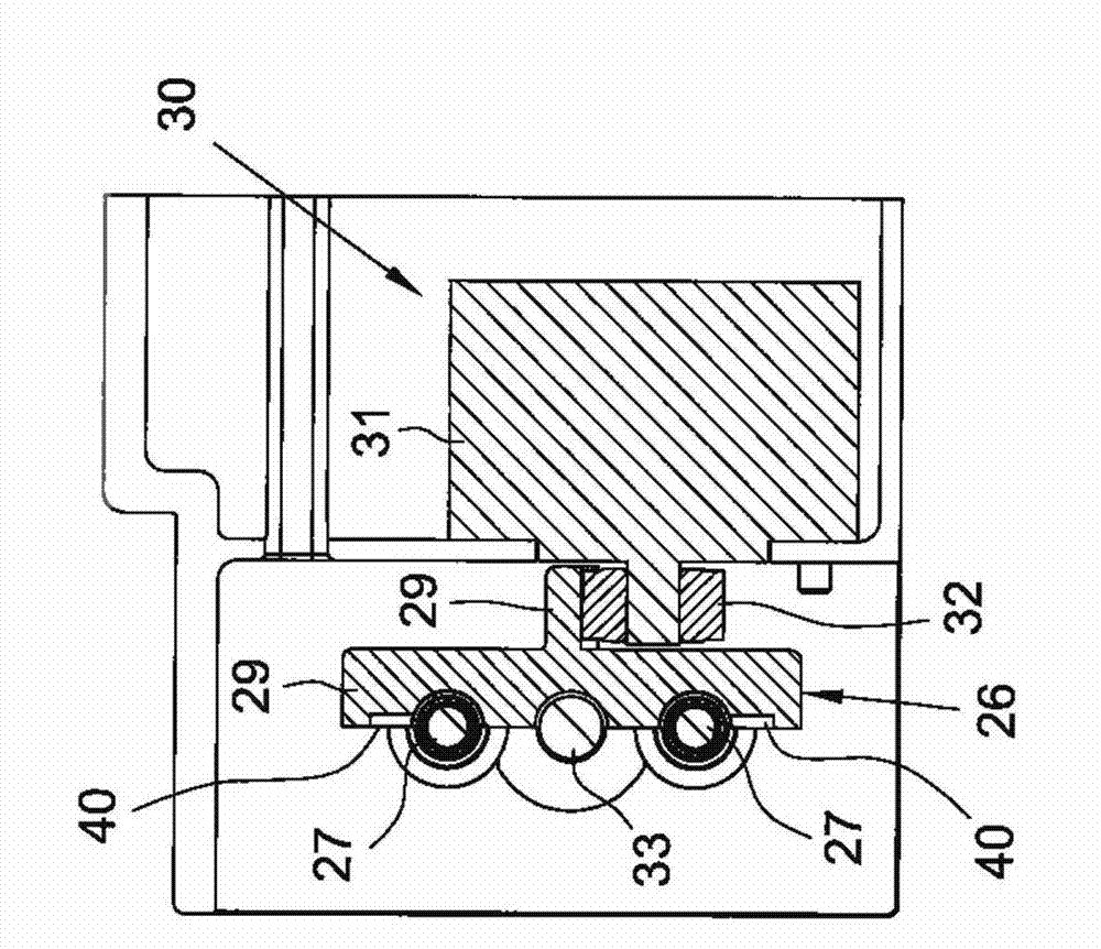
[0030] figure 1 A side view of a spool unit is schematically shown and shows a technical problem. Figure 2A -C shows the solution of the wire tensioning device according to the invention inserted in the winding station. Figure 2A shows the front view of the device, while Figure 2B A section according to A-A is shown. Figure 2C An isometric view of the device is shown in more detail.

[0031] Alternatively, the idea according to the technical solution of the present invention can be based on image 3 The scheme of the structure shown in is made, according to image 3 The scheme of the structure shown in is identical to the scheme according to FIG. 2 .

[0032] Figure 4 is an exampl...


PUM


Abstract

Device for tensioning a winding thread (2) in textile machines comprising a plurality of stationary deviator elements (22, 54) and a plurality of displaceable deviator elements (27, 47) arranged like a comb facing one another in a staggered and opposed manner so as to form a tortuous path for the thread that passes through the device, in which such deviator elements are provided with sliding elements (38) elastically contrasted to move forth and back against the thread, each sliding element (38) being capable of moving independently from each other, in which the tortuousness of the path is adjusted with a mobile device (26) that modulates the load of the elastic elements (39, 49) working in contact with the thread, to obtain the desired tension in the thread in outlet from the thread tensioning device.

Description

technical field [0001] The present invention relates to a device for generating and adjusting the tension (known as tensioning) of a winding thread in a textile machine. Background technique [0002] In the textile industry, many processes of producing and trimming yarns require adjusting the tension of the winding thread, however, in order to make the technical problems addressed and solved by the present invention and the characteristics and advantages of the present invention over the prior art more clear, The invention is described hereinafter with reference to a winding process carried out in a winder in which the processed thread is unwound from a bobbin and rewound in a package (package). As is known, a winder comprises a plurality of bobbin units arranged along the front of the machine and provided with common control and maintenance equipment. [0003] The base part of the spool unit is in the figure 1 As shown in , those components not directly related to the tec...

Claims


Application Information

Patent Timeline
Patent Type & Authority Applications(China)
IPC IPC(8): B65H59/10
CPCB65H2701/31B65H59/28
Inventor 罗伯托·巴迪亚利斯特凡诺·马尔凡特乔瓦尼·加迪恩保罗·加斯帕尔多
Owner SAVIO MACCHINE TESSILI
Learn More