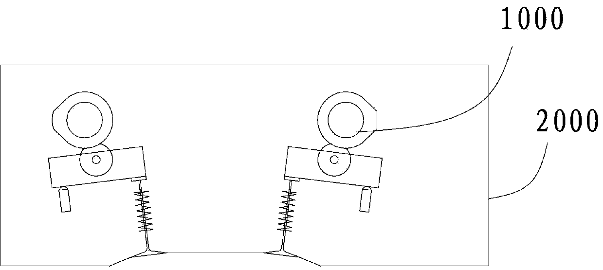
Engine and actuating mechanism of variable valve lift device thereof

A valve lift, actuating mechanism technology, applied in the direction of engine components, machines/engines, non-mechanically actuated valves, etc., can solve the problems of poor adjustment accuracy, high reliability requirements, and high cost, and achieve high precision, driving Reliable process and simple structure

Active Publication Date: 2013-10-23
GREAT WALL MOTOR CO LTD
View PDF6 Cites 0 Cited by
  • Summary
  • Abstract
  • Description
  • Claims
  • Application Information

AI Technical Summary

Problems solved by technology

[0003] The existing non-continuously variable valve lift structure has a single lift mode, which cannot realize most of the engine's working conditions, and the fuel saving effect is not obvious
However, the existing continuously variable valve lift technology has high cost of parts and complex structure, and requires high reliability of each part. The design of the engine cylinder head is more difficult, especially the structure of the actuating mechanism is more complicated, and its adjustment The process is not easy to control and the adjustment accuracy is poor

Method used


Image

  • Engine and actuating mechanism of variable valve lift device thereof
  • Engine and actuating mechanism of variable valve lift device thereof
  • Engine and actuating mechanism of variable valve lift device thereof

Examples


Embodiment Construction

[0045] Embodiments of the present invention are described in detail below, examples of which are shown in the drawings, wherein the same or similar reference numerals designate the same or similar elements or elements having the same or similar functions throughout. The embodiments described below by referring to the figures are exemplary and are intended to explain the present invention and should not be construed as limiting the present invention.

[0046] In describing the present invention, it should be understood that the terms "center", "longitudinal", "transverse", "length", "width", "thickness", "upper", "lower", "front", " Orientation or position indicated by "back", "left", "right", "vertical", "horizontal", "top", "bottom", "inner", "outer", "clockwise", "counterclockwise", etc. The relationship is based on the orientation or positional relationship shown in the drawings, and is only for the convenience of describing the present invention and simplifying the descrip...


PUM


Abstract

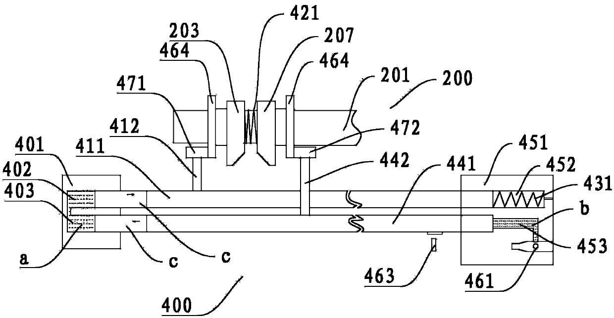
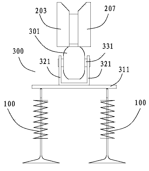
The invention discloses an engine and an actuating mechanism of a variable valve lift device thereof. The actuating mechanism comprises a first hydraulic valve block, a first driving rod, a second driving rod, an elastic resetting device and an elastic piece, wherein the first hydraulic valve block is internally provided with a first valve cavity and a second valve cavity which are the same in shape and are mutually communicated, and the first valve cavity and the second valve cavity are filled with liquid; one end of the first driving rod extends into the first valve cavity from one end of the first valve cavity, the first driving rod and the first valve cavity are in sealing fit and can relatively move, and a first shifting fork is arranged on the first driving rod; one end of the second driving rod extends into the second valve cavity, the second driving rod and the second valve cavity are in sealing fit and can relatively move, and a second shifting fork is arranged on the second driving rod; the elastic resetting device is positioned at the other end of the first driving rod; and the elastic piece is elastically abutted between a first cam and a second cam. The actuating mechanism disclosed by the invention has the advantages of simple structure, reliable control and high precision.

Description

technical field [0001] The invention relates to the technical field of automobile construction, in particular to an actuating mechanism for a variable valve lift device of an engine. Background technique [0002] In the valve drive mechanism of traditional engines, the valve timing is generally determined based on the local optimization of a narrow operating range of the engine, which is fixed during the working process, and the valve movement law is completely determined by the cam profile. However, the traditional gasoline engine has a single cam profile and cannot adjust the intake air volume according to the engine load. The valve operating parameters of the traditional engine valve train are also fixed, and the determination of the parameters depends on the designed operating point. [0003] The existing non-continuously variable valve lift structure has a single lift mode, which cannot realize most of the working conditions of the engine, and the fuel saving effect is...

Claims


Application Information

Patent Timeline
Patent Type & Authority Applications(China)
IPC IPC(8): F01L9/02F01L9/11
Inventor 崔亚彬胡佳明张昊
Owner GREAT WALL MOTOR CO LTD
Why Eureka
Try Eureka