Bicycle control apparatus

a control apparatus and bicycle technology, applied in the direction of vehicle position/course/altitude control, process and machine control, instruments, etc., can solve the problems of inability to perform gearshift action, and inability to exert excessive force on the transmission, etc., to achieve reliable

Active Publication Date: 2014-08-07
SHIMANO INC
View PDF5 Cites 15 Cited by
  • Summary
  • Abstract
  • Description
  • Claims
  • Application Information

AI Technical Summary

Benefits of technology

[0011]In accordance with a fourth aspect of the present invention, the bicycle control apparatus according to the second or third aspect is configured so that the controller is programmed to set the prescribed value in relation to a maximum value at which an internal transmission can shift gears, where the internal transmission is provided to a rear wheel of the bicycle. An internal transmission commonly stands a cam upright and lays the cam sideways to select a shift position. When excessive rotational force acts on the cam at this time, t e gearshift action cannot be performed. Because the gearshift action is performed when the combined value of the first rotational force and the second rotational force decreases to or below the maximum value at which the internal transmission can shift gears, the gearshift action can be performed reliably in the internal transmission.
[0012]In accordance with a fifth aspect of the present invention, the bicycle control apparatus according to the fourth aspect is configured so that the controller is programmed to set the prescribed value to a range of 50 to 100 percent of the maximum value. The second rotational force can thereby be reduced by a lower percentage.
[0013]In accordance with a sixth aspect of the present invention, the bicycle control apparatus according to the fifth aspect is configured so that the controller is programmed to set the prescribed value to a range of 80 to 100 percent of the maximum value. The second rotational force can thereby be reduced by a lower percentage.

Problems solved by technology

When excessive rotational force acts on the cam at this time, t e gearshift action cannot be performed.
When only the first rotational force exceeds the prescribed value, there is a risk that excessive force will act on the transmission and the gearshift action will not be possible, and the load imposed on the gearshift action of the bicycle control apparatus can therefore be suppressed by inhibiting the gear shifting by the transmission.

Method used


Image

  • Bicycle control apparatus
  • Bicycle control apparatus
  • Bicycle control apparatus

Examples


second embodiment

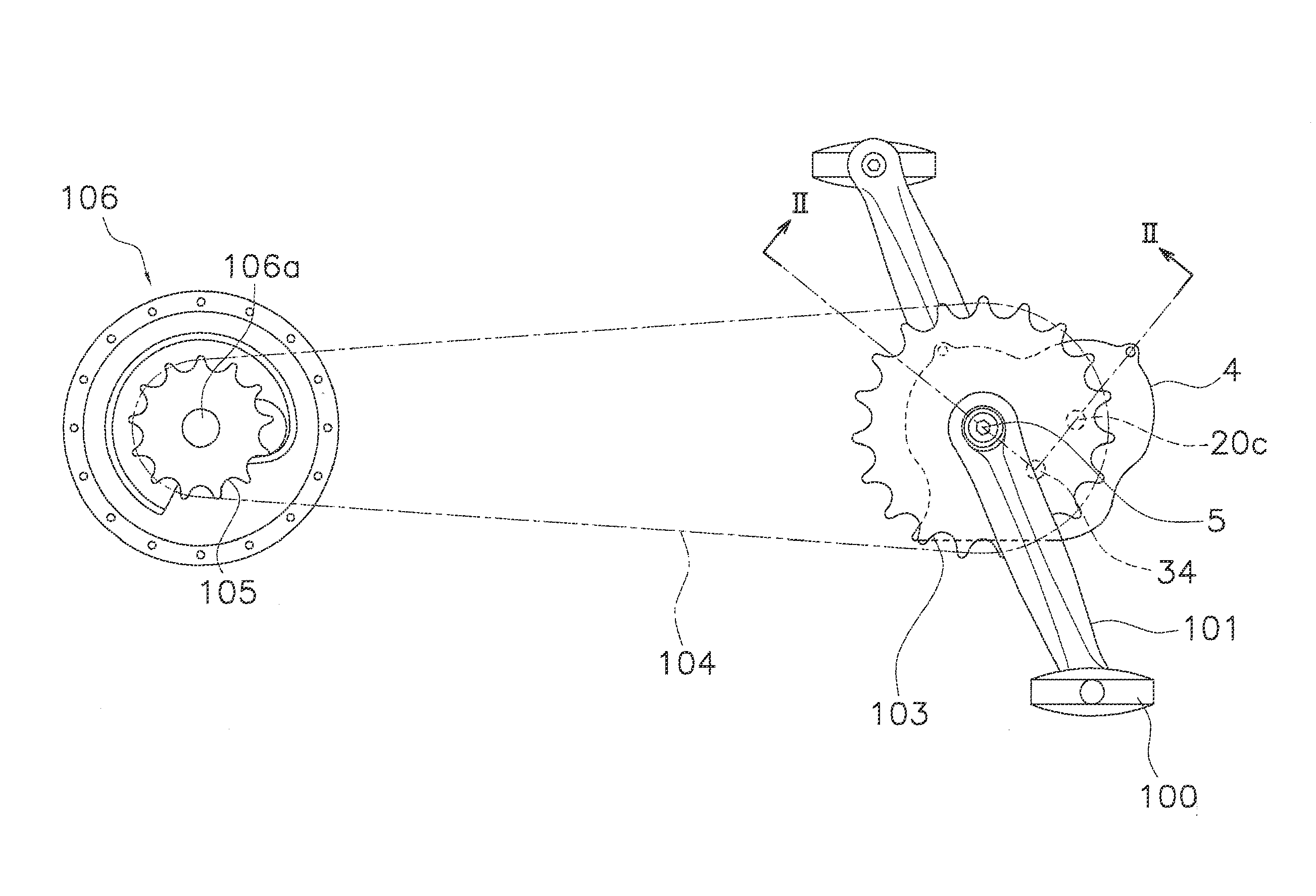
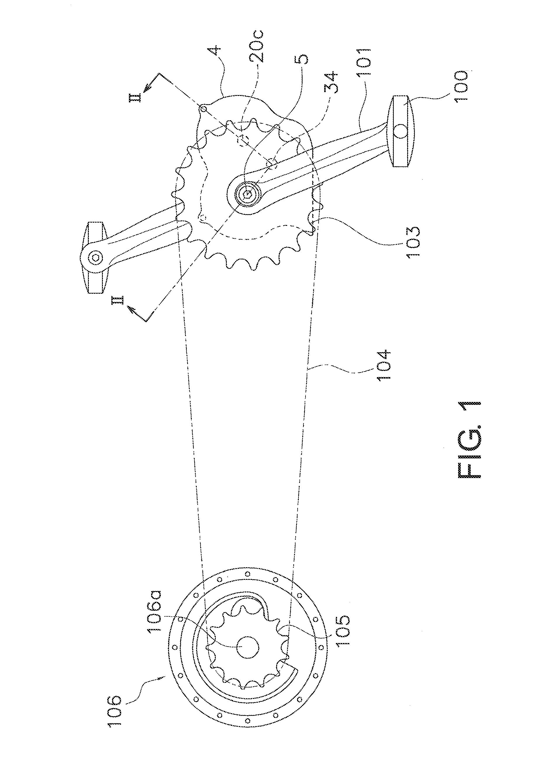
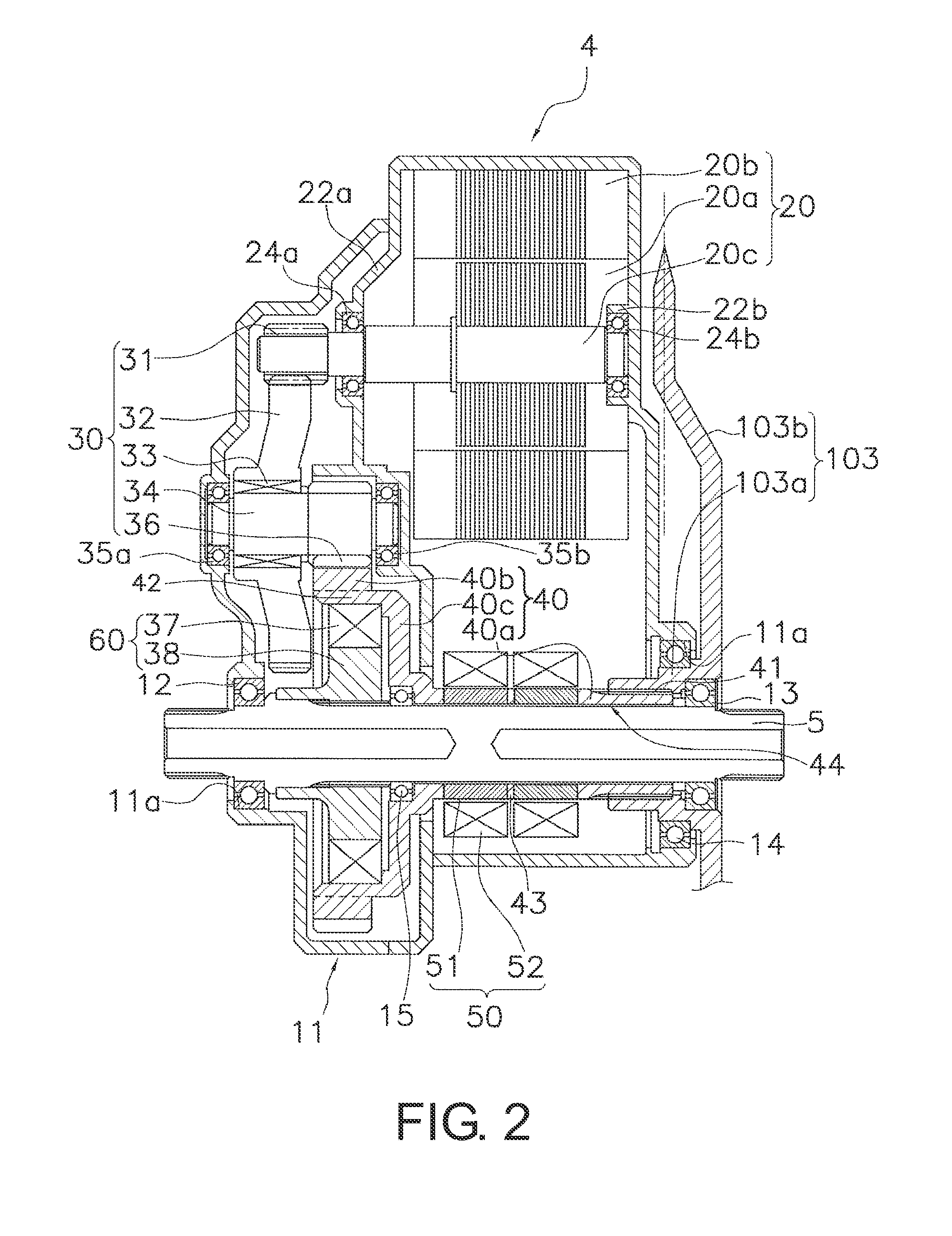
[0075]In the second embodiment, a bicycle control apparatus 210 is configured including a motor controller 210a for controlling the motor 20, a gearshift controller 210b for controlling the internal gearshift hub 106, and a torque sensor 50, as shown in FIG. 6. Therefore, the motor 20 and the internal gearshift hub 106 are controlled individually by two controllers (the motor controller 210a and the gearshift controller 210b), and communication between the two controllers is performed to perform the process of reducing the assist torque T2 during the gearshift action. The motor controller 210a and the gearshift controller 210b have the same configuration as the controller 110a; for example, the two controllers are each configured including a central processing unit (CPU) and a memory on which predetermined programs are recorded. The gearshift controller 110a preferably actuates during the gearshift action, and therefore actuates in a power conservation mode aside from the time perio...


PUM


Abstract

A bicycle control apparatus is basically provided for controlling a bicycle in which a first rotational force of a crank and a second rotational force of an electric riding assistance motor for riding assistance are transmitted to a rear sprocket. The bicycle control apparatus includes a rotational force detector and a controller. The rotational force detector is configured to detecting the first rotational force imparted to the bicycle crank. The controller is programmed to reduce the second rotational force of the electric riding assistance motor to actuate a transmission of the bicycle in accordance with the first rotational force detected by the rotational force detector.

Description

BACKGROUND[0001]1. Field of the Invention[0002]This invention generally relates to a bicycle control apparatus. More specifically, the present invention relates to a bicycle control apparatus for controlling a bicycle in which a first rotational force of a crank and a second rotational force of an electric riding assistance motor for riding assistance are transmitted to a rear sprocket.[0003]2. Background Information[0004]An example of a bicycle control apparatus is disclosed in Japanese Laid-Open Patent Publication No. 2001-10582 for controlling an electrically assisted bicycle in which an electric motor for riding assistance is used to assist pedaling force. The electric motor for riding assistance of the electrically assisted bicycle according to Japanese Laid-Open Patent Publication No. 2001-10582 is disposed in the periphery of a crank axle of the frame of a bicycle. The electrically assisted bicycle has a transmission driven by an electric actuator, and a pedaling force sensor...

Claims


Application Information

Patent Timeline
Patent Type & Authority Applications(United States)
IPC IPC(8): B60L15/20
CPCB60L15/20B62M6/45B62M6/50B62M6/55B60L50/20Y02T10/72B62M6/90
Inventor TSUCHIZAWA, YASUHIRO
Owner SHIMANO INC
Why Eureka
Try Eureka