Device for decanting a liquid

a liquid and device technology, applied in the field of liquid decanting devices, can solve the problems of only being suitable for decanting solid granulate but not, unable to meet the needs of decanting solid granulate, etc., to achieve the greatest possible flow cross section, reduce the pressure on the flange collar, and measure accurately

Active Publication Date: 2006-03-21
ANDREAS STIHL AG & CO KG
View PDF7 Cites 18 Cited by
  • Summary
  • Abstract
  • Description
  • Claims
  • Application Information

AI Technical Summary

Benefits of technology

[0007]According to a feature of the invention, a valve plate is provided for blocking the flow path at a free end of the support. Tension rods are coupled to the relative movement of the inner and outer sleeves of the support and are provided next to the edge of the valve plate. The tension rods are provided for pressing the valve plate from its valve seat against the spring force. When the support is opened by pressing against the valve plate, then almost the entire cross section of the support is available for the discharge of the liquid so that a maximum volume flow can be achieved. In the decanting device of the invention, the volume flow is determined by the stroke of the valve plate, that is, the distance of the valve plate from its valve seat at the end of the support and the volume flow can be metered accurately in this way. To end the decanting operation, the pressure on the flange collar is reduced and the tension rods pull the valve plate against the valve seat under the action of the spring force whereby a further discharge of liquid is immediately prevented. In the configuration of the support of the invention, a further discharge of liquid is also automatically prevented as soon as the liquid level in the vessel reaches the support.
[0008]Preferably, two diametrically mounted tension rods are provided whereby the greatest possible flow cross section can be made available with a stable position and actuability of the valve plate. Advantageously, the tension rods are charged by the inner sleeve in the decanting device of the invention so that a compact configuration is provided. The tension rods are advantageously expandable and are equipped at their ends with radial catches for pressing and pulling the valve plate. The catches are latched in an undercut configured on the inner sleeve. In this way, the assembly of the decanting device is facilitated in that the valve plate with the pull rods formed thereon is inserted into the inner sleeve and there latches automatically. The valve plate with the tension rods is manufactured as a single piece in a preferred embodiment and is especially made of plastic as an injection molded part.
[0009]A further increase of the volume flow is possible by configuring one of the tension rods to have a radial opening in the region of the valve plate to which opening a venting line is connected which runs in the interior of the support. The venting line is led along the wall of the support interior and, in this way, further provides the optimal flow cross section of the support interior.
[0010]According to the invention, the outer sleeve surrounds the inner sleeve to form an annular space wherein a helical spring is mounted. In this way, the outer and inner sleeves can be manufactured with low manufacturing cost as parts which are inserted one into the other, for example, as injection molded parts. Seals which may be required can be seated in the annular gap for accommodating the helical spring. The inner sleeve is advantageously guided on the outer sleeve so that it cannot rotate with respect thereto in order to provide a more stable guidance of the inner sleeve in the outer sleeve and therefore a reliable actuation of the decanting device.
[0011]Advantageously, the connection and securing of the outer sleeve to the inner sleeve is achieved with a bayonet connection or the like. Here, it is advantageous to provide a rotational sleeve on the outer sleeve which engages over the inner sleeve with at least one radial catch. The inner sleeve here is accommodated in the outer sleeve.

Problems solved by technology

The known closure cap may facilitate the filling of internal combustion engines with oil from small oil canisters; however, the supplied liquid quantity cannot be metered so that the problem occurs that the vessel, which is to be filled, can overflow.
However, for the filling of liquids, such a device can be used only in a limited way or not at all because a controlled outflow without leakage cannot be effected.
This procedure is only suitable for decanting solid granulate but not for liquids which would continue to flow out with a fully refilled vessel.
Furthermore, a precise metering with the known device is not possible because the substance, which is already in the support, still arrives in the refill vessel.

Method used


Image

  • Device for decanting a liquid
  • Device for decanting a liquid
  • Device for decanting a liquid

Examples


Embodiment Construction

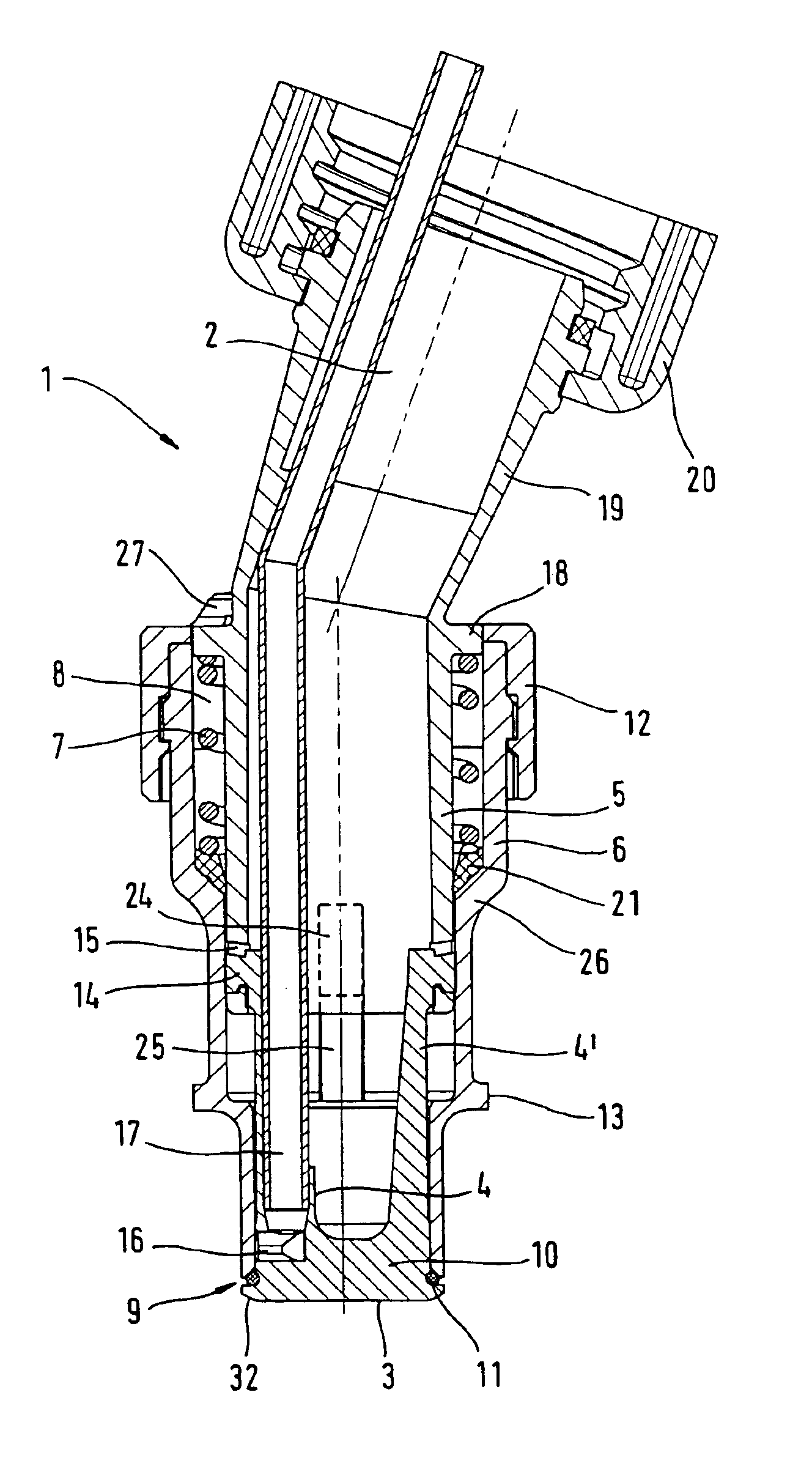
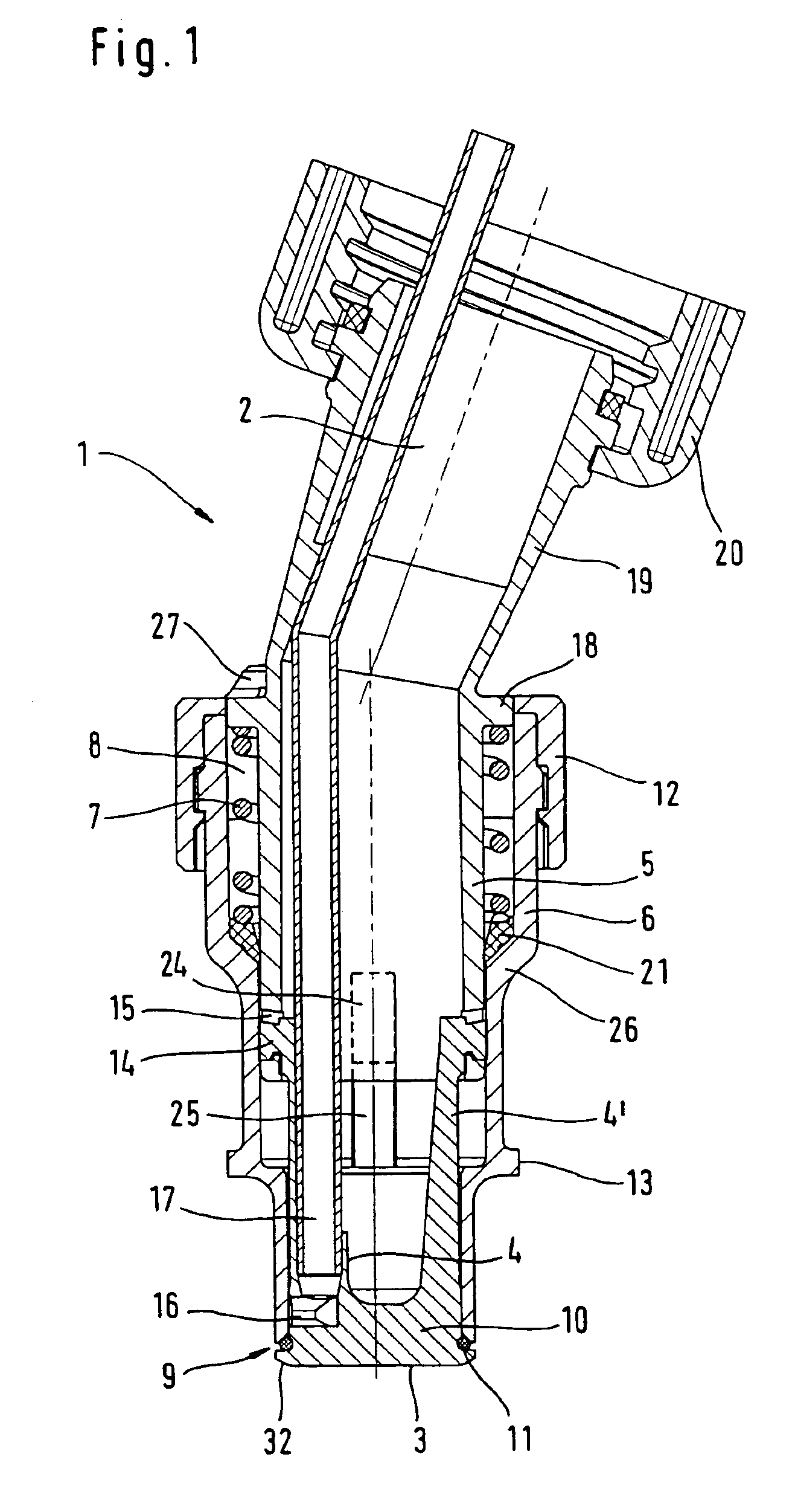
[0017]The device for decanting fluids shown in FIG. 1 includes a tubular-shaped support 1 whose flow channel 2 has an essentially homogeneous pass-through cross section in the interior and so permits an optimal discharge of the liquid toward the free end 9 of the support 1. A nut 20 for threadably pipe-connecting the support 1 to a supply vessel or a feed line for fuel or lubricating oil is provided at the upper end of the support. The free end 9 of the support is configured as a valve seat. The flow channel 2 is blocked by a valve plate 3 which lies against the free end 9 of the support with its edge 32 and with a sealing ring 11 disposed in between. For lifting the valve plate 3, an inner sleeve 5 is provided in the forward part reaching to the free end 9 of the support. The inner sleeve 5 is essentially rotationally symmetric and is inserted into the outer sleeve and lies segment wise in overlapment with the outer sleeve 6. The inner sleeve 5 is axially displaceable relative to t...


PUM

PropertyMeasurementUnit
resilient biasingaaaaaaaaaa
biasing forceaaaaaaaaaa
forceaaaaaaaaaa

Abstract

An arrangement for decanting liquids includes a tubular-shaped support (1) having a flow channel (2). The flow channel (2) is blocked by a valve plate (3) which is coupled via axial connecting elements (4, 4′) to the relative movement of an inner sleeve (5) and an outer sleeve (6) of the support (1). The outer sleeve (6) lies in overlapment and the axial connecting elements (4, 4′) extend into the interior of the support. The valve plate (3) can be lifted from its valve seat against a spring force engaging at the inner sleeve (5) and at the outer sleeve (6). A radial flange collar (13) is formed on the outer sleeve (6). To ensure an accurate metering at the highest possible volume flow of the discharged liquid at low manufacturing costs, the valve plate (3) is mounted at a free end (9) of the support (1) and the axial connecting elements are configured as tension rods (4, 4′) and are arranged next to an edge of the valve plate (3).

Description

FIELD OF THE INVENTION[0001]The invention relates to an arrangement for decanting liquids, especially fuels and lubricants.BACKGROUND OF THE INVENTION[0002]Decanting devices for preventing leaks are utilized when filling fuel or a lubricant, for example, into a supply vessel of an internal combustion engine provided therefor. The decanting device is introduced with a support into an opening of the vessel to be filled. The opening of the vessel is provided for this support.[0003]European patent publication 0 103 600 discloses a cap for a liquid vessel which is configured as a hollow body having a flange collar and is seated on a central outlet opening of a supply vessel. The base of the cap lies in the outlet opening of the supply vessel. The periphery of the pot-shaped cap is provided with pass-through openings between the radial flange collar and the base of the cap. If the flange collar is pressed down upon a vessel, which is to be filled, by seating the cap, then the region of th...

Claims


Application Information

Patent Timeline
Patent Type & Authority Patents(United States)
IPC IPC(8): B65B1/04B67D7/00B67D7/04B67D7/06B67D7/36
CPCB67D7/005
Inventor SCHLIEMANN, HARALDNICKEL, HANS
Owner ANDREAS STIHL AG & CO KG
Why Eureka
Try Eureka