Variable spray hole type electric control oil sprayer

An electronically controlled fuel injection and fuel injector technology, which is applied in the direction of machines/engines, fuel injection devices, engine components, etc., can solve the problem of inaccurate control of small fuel injection volume, poor diesel engine effect, high control accuracy and response speed, etc. problem, to achieve the effect of improving fuel injection effect, improving power and economy

Inactive Publication Date: 2013-10-23
HARBIN ENG UNIV
View PDF6 Cites 3 Cited by
  • Summary
  • Abstract
  • Description
  • Claims
  • Application Information

AI Technical Summary

Problems solved by technology

Although the widely used diesel engine electronically controlled fuel injectors respond quickly and have flexible fuel injection characteristics, which improve the power and economy of diesel engines compared with mechanical fuel injectors, there are also shortcomings: 1. Due to its influence on the amount of oil The control of the control is carried out entirely by changing the pulse width of the control signal of the electronically controlled actuator, so that the small fuel injection has higher requirements on the control accuracy and response speed of the electronically controlled actuator, and the control of the small fuel injection is not accurate enough, resulting in diesel engine failure. The effect of small fuel injection and multiple injections is poor; 2. The fuel injection characteristics can only be changed by changing the form of the control signal, which makes the control process more complicated

Method used


Image

  • Variable spray hole type electric control oil sprayer
  • Variable spray hole type electric control oil sprayer
  • Variable spray hole type electric control oil sprayer

Examples


Embodiment Construction

[0013] The present invention will be described in more detail below in conjunction with the accompanying drawings:

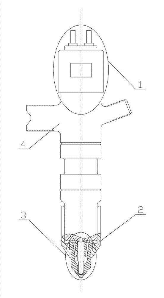
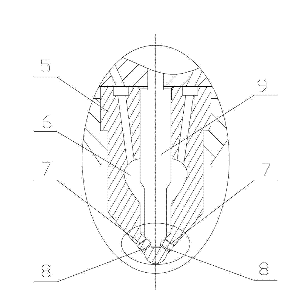
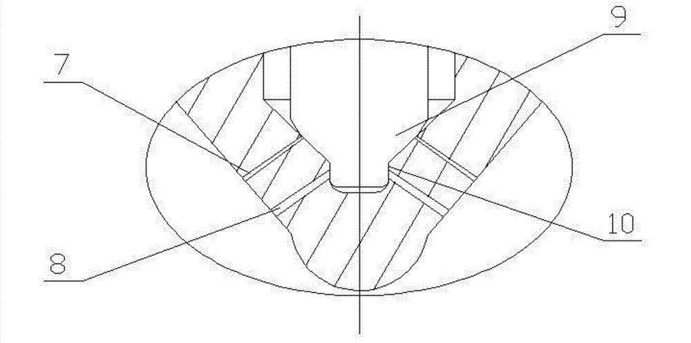
[0014] combine figure 1 ~3, the variable nozzle type electronically controlled fuel injector of the present invention is composed of an electronically controlled actuator part 1 , a fuel injector body 4 and a fuel injection nozzle 3 . The electronically controlled actuator part 1 is located above the fuel injector body 4, and controls the fuel injection timing and fuel injection quantity of the fuel injector by receiving control signals. The fuel injector 3 is located under the fuel injector body 4 and is connected to the fuel injector body 4 through the tight cap 2 . The fuel injection nozzle 3 includes a needle valve 9 and a fuel injection nozzle needle valve base 5, and an oil holding groove 6 is formed between the two, which is respectively communicated with the oil inlet oil passage and the oil injection hole. There are two rows of fuel injection holes at...


PUM


Abstract

The invention aims at providing a variable spay hole type electric control oil sprayer which comprises an electric control actuator part, an oil nozzle and an oil sprayer body, wherein the electric control actuator part and the oil nozzle are mounted at the upper end and the lower end of the oil sprayer body respectively; the oil nozzle comprises a needle valve and a needle valve base; the needle valve is mounted in the needle valve base; an oil containing groove is formed by the needle valve and the needle valve base; main oil spray holes and auxiliary oil spray holes are formed at the lower end part of the needle valve base from the bottom up sequentially; a double sealing surface structure is arranged at the lower end part of the needle valve; a bevelled sealing surface and a cylindrical sealing surface are arranged at the lower end part of the needle valve from the top down sequentially; when the needle valve is positioned at the undermost end of a stroke, the cylindrical sealing surface seals the main oil spray holes, and the bevelled sealing surface seals the auxiliary oil spray holes; and when the needle valve ascends, the auxiliary oil spray holes are communicated with the oil containing groove earlier than the main oil spray holes. The oil sprayer facilitates controlling small oil quantity spray in a multi-spray process, and can allow main spray to be combined with boot type spray, so that an oil spray effect is improved, the power performance and the economical efficiency of an engine are improved, and stricter discharge laws and regulations are met.

Description

technical field [0001] The invention relates to a diesel engine, in particular to a fuel injector of the diesel engine. Background technique [0002] In recent years, with the increasingly strict emission regulations and the rapid development of electronic control technology, electronically controlled injectors have been widely used in diesel fuel systems. The electronically controlled actuator responds quickly and can quickly and accurately control the fuel injection quantity and fuel injection pattern of the diesel engine, thereby improving the economy and power of the diesel engine and reducing the emission of harmful substances during the working process. [0003] The current application of diesel electronically controlled injectors is to control the shut-off and opening of the oil drain circuit in the control chamber of the injector through the electronically controlled actuator, thereby achieving the purpose of adjusting the fuel injection amount and changing the fuel ...

Claims


Application Information

Patent Timeline
Patent Type & Authority Applications(China)
IPC IPC(8): F02M51/06
Inventor 王昊范立云白云刘鹏王天阳张建宇仇会彬连历马修真
Owner HARBIN ENG UNIV
Why Eureka
Try Eureka