
Automobile drum type brake heat dissipation system

A heat dissipation system, drum-type technology, applied in the direction of brake type, brake parts, mechanical equipment, etc., can solve the problems of reducing vehicle carrying capacity, icy road traffic accidents, increasing the extra load of the car, etc., to ensure stable and normal performance Operation, reduce transportation costs, improve the effect of carrying capacity

Inactive Publication Date: 2013-10-23
十堰龙腾达工业有限公司
View PDF7 Cites 10 Cited by
  • Summary
  • Abstract
  • Description
  • Claims
  • Application Information

AI Technical Summary

Problems solved by technology

However, adding a water tank increases the extra load of the car on the one hand, reduces the limited carrying capacity of the vehicle, and at the same time brings inconvenience and trouble to road safety and vehicle maintenance, and there are also safety hazards caused by the failure of the sprinkler device or improper operation. Hidden danger
When encountering cold weather, the pipeline of the sprinkler device will often be unable to work normally due to freezing, or the local ice on the road surface will cause traffic accidents due to the cooling of the spraying water
In addition, the sudden cooling of the brake drum by spraying water in the high temperature state will easily cause the brake drum to break, and even cause the brake to fail, which will bring serious consequences to the driving of the vehicle and life and property.

Method used


Image

  • Automobile drum type brake heat dissipation system
  • Automobile drum type brake heat dissipation system
  • Automobile drum type brake heat dissipation system

Examples


Embodiment Construction

[0016] Embodiments of the present invention will be further described below in conjunction with the accompanying drawings.

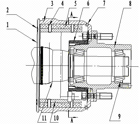
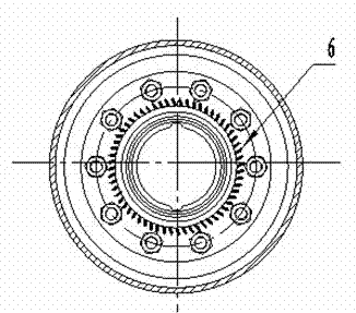
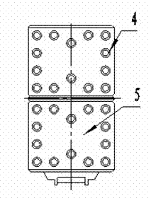
[0017] It includes an axle 11, the axle is installed with the hub 8 through the bearing 9, the inner side of the hub is connected with the brake drum 3 through the flange plate with the connecting bolt, the inner cavity of the brake drum is equipped with a brake shoe, and the brake shoe includes The brake shoe 10 and the friction plate 5, the friction plate and the brake shoe are riveted together through the rivet 4 with a through hole, so that the heat generated between the brake shoe and the brake drum can be dissipated in time, and the heat dissipation effect is further enhanced Install a wind wheel or fan blade 6 near the bottom of the brake drum inner cavity, the wind wheel or fan blade is connected with the brake drum through the connecting bolts of the brake drum and the hub, and runs synchronously with the hub brake drum; Air intake holes 7 are p...


PUM


Abstract

The invention relates to an automobile drum type brake heat dissipation system, and belongs to the technical field of automobile brakes. The automobile drum type brake heat dissipation system comprises an axle, a hub, a brake drum and a brake shoe, wherein the hub is connected with the brake drum, the brake shoe is configured in an inner cavity of the brake drum, and the automobile drum type brake heat dissipation system is characterized in that a wind wheel or a fan blade is arranged in the inner cavity of the brake drum, an air inlet is formed in the outer side of the brake drum, and an air outlet is formed in the other side of the brake drum. The automobile drum type brake heat dissipation system achieves forced ventilation heat dissipation in the inner cavity of the relatively-sealed brake drum, the exterior cold air can continuously enter the inner cavity of the brake drum, the effects of heat dissipation and cooling are achieved, and therefore performance stability and normal operation of the automobile brake system are ensured. The forced ventilation of the inner cavity of the brake drum enables the inner cavity of the brake drum to keep clean and the good ventilation effect, and the heat dissipation effect of the automobile drum type brake can be further improved. The automobile drum type brake heat dissipation system is simple in structure, reasonable in design, reliable in use performance, safe and reliable in operation, long in service life, capable of conveniently conducting refit on an existing automobile, and beneficial to saving energy and protecting environment.

Description

technical field [0001] The invention relates to an automobile drum brake cooling system, which belongs to the technical field of automobile braking. Background technique [0002] Automobile drum brakes are still widely used in trucks because of their simple structure, large braking torque, low manufacturing cost, and convenient maintenance. Although the existing drum brakes of automobiles have been improved for many times and their braking performance has been perfected, there are still certain problems in the heat dissipation after friction braking when braking or emergency braking under heavy loads. Accidents of brake failure due to high temperature generated by braking often occur, which has become a major safety hazard in vehicle driving. In order to solve the above-mentioned problems, the current heat dissipation and cooling method of automobile drum brakes is to install a water storage tank and a water spray device on the vehicle, and to achieve the purpose of forced ...

Claims


Application Information

Patent Timeline
IPC IPC(8): F16D65/827
Inventor 夏海龙
Owner 十堰龙腾达工业有限公司
Learn More