Hydraulic transmission device
A technology of hydraulic transmission device and transmission mechanism, applied in the field of transmission, which can solve problems such as single function and uncontrollable clutch output torque, and achieve the effect of stable start, simple structure and high efficiency
- Summary
- Abstract
- Description
- Claims
- Application Information
AI Technical Summary
Problems solved by technology
Method used
Image

Examples
Embodiment 1
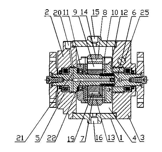
[0030] exist figure 1 In the shown embodiment, a hydraulic transmission device includes a housing 1, a front cover 2 and a rear cover 3 cooperating with the housing 1, the housing 1 and the front cover 2 or the rear cover 3 are of a split structure, and the housing A cavity 4 is provided on the body 1, and a transmission mechanism is provided inside the cavity 4. The transmission mechanism includes an input shaft 5, an output shaft 6, a rotor 7 and a swivel 8. The rotor 7 and the input shaft 5 are separate structures, and the swivel 8 It is a separate structure from the output shaft 6, and the housing is a separate structure from the front cover or rear cover. The rotor 7 is arranged on the input shaft 5 and rotates together with the input shaft 5, the swivel 8 is arranged on the outside of the rotor 7 and connected with the output shaft 6, the swivel 8 rotates together with the output shaft 6, and the rotor 7 is provided with several sliding vanes 9. The inner surface of the...
Embodiment 2
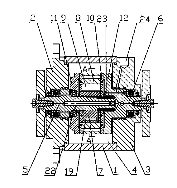
[0034] exist Image 6 In the shown embodiment, a hydraulic transmission device includes a housing 1, a front cover 2 and a rear cover 3 cooperating with the housing 1, the housing 1 and the front cover 2 or the rear cover 3 are of a split structure, and the housing A cavity 4 is provided on the body 1, and a transmission mechanism is provided inside the cavity 4. The transmission mechanism includes an input shaft 5, an output shaft 6, a rotor 7 and a swivel 8. The rotor 7 and the input shaft 5 are separate structures, and the swivel 8 and the output shaft 6 are split structures, and the housing and the front cover or rear cover are split structures. The rotor 7 is arranged on the input shaft 5 and rotates together with the input shaft 5. The swivel 8 is arranged on the outside of the rotor 7 and connected with the output shaft 6. The swivel 8 rotates together with the output shaft 6. The rotor 7 is provided with several Towards the sliding blades 9, the inner surface of the s...
Embodiment 3
[0038] The content of embodiment 3 is basically the same as that of embodiment 1, except that the transmission mechanism does not have a bimetallic side plate 10, which can simplify the structure of the hydraulic transmission device. The swivel and the output shaft are integrally structured, and the housing is integrally structured with the front cover or the rear cover.
[0039] The swivel of the hydraulic transmission device is connected to the output shaft and can rotate together with the output shaft. The swivel and the rotor compress the hydraulic oil along the contour of the swivel to transmit the rotational force to the swivel. Since the torque is equal to the pressure x displacement , so controlling the input pressure controls the output torque.
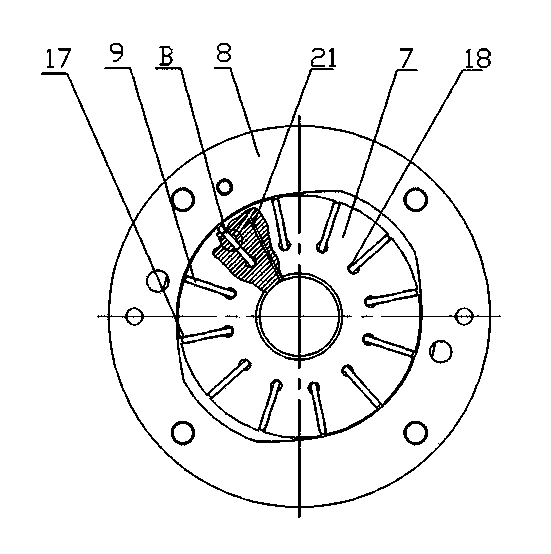
[0040] When the hydraulic transmission is in use, the input shaft, rotor and vanes rotate together, and the swivel, pressure side plate and output shaft rotate together. Since the inner surface of the swivel 8 is provided wi...
PUM
 Abstract
Description
Claims
Application Information
 - R&D
- Intellectual Property
- Life Sciences
- Materials
- Tech Scout
- Unparalleled Data Quality
- Higher Quality Content
- 60% Fewer Hallucinations
Browse by: Latest US Patents, China's latest patents, Technical Efficacy Thesaurus, Application Domain, Technology Topic, Popular Technical Reports.
© 2025 PatSnap. All rights reserved.Legal|Privacy policy|Modern Slavery Act Transparency Statement|Sitemap|About US| Contact US: help@patsnap.com