Supercharge Your Innovation With Domain-Expert AI Agents!

Temperature control switch test circuit

A technology of temperature control switch and test circuit, which is applied in the direction of circuit breaker test, etc., can solve the problems of increasing labor intensity of experimenters and low test efficiency, and achieve the effects of improving test efficiency, shortening on-off cycle, and reducing labor intensity

Inactive Publication Date: 2016-09-07
OCEANKING DONGGUAN LIGHTING TECH +2
View PDF4 Cites 0 Cited by
  • Summary
  • Abstract
  • Description
  • Claims
  • Application Information

AI Technical Summary

Problems solved by technology

[0003] Based on this, it is necessary to provide an unattended, unattended system for the problem that when testing the on-off life of the temperature control switch, the experimenter is always required to record the number of on-off times, which makes the test efficiency low and increases the labor intensity of the experimenter. Temperature control switch test circuit with high test efficiency

Method used


Image

  • Temperature control switch test circuit
  • Temperature control switch test circuit

Examples


Embodiment Construction

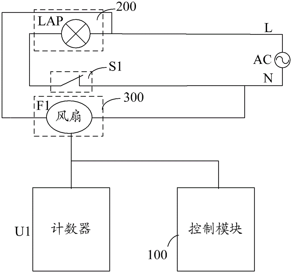
[0030] Such as figure 1 Shown is a temperature control switch test circuit of an embodiment. The temperature control switch test circuit includes a control module 100 , a counter U1 , a heat source 200 , a heat source 300 and a voltage conversion module 400 .

[0031] The heat source 200 and the temperature control switch S1 are connected in series at the two poles of the power supply, and the temperature control switch S1 is located close to the heat source 200 and the heat dissipation source 300;

[0032] The input terminal of the control module 100 is connected to the input of the power supply, and the control terminal of the control module 100 is connected to the heat dissipation source 300 and the counter U1 at the same time, and is used to control the counter U1 to record the temperature control according to the state of the heat source 200 following the opening and closing of the temperature control switch S1. The on-off times of the switch S1, and the control module 1...


PUM


Abstract

The invention relates to a temperature controlled switch testing circuit, which comprises a control module, a counter, a heat producing source and a heat dissipation source, wherein the heat producing source and a temperature controlled switch are connected to two electrodes of a power supply in series, and the temperature controlled switch is located at the position close to the heat producing source and the heat dissipation source; a control end of the control module is connected with the heat dissipation source and the counter simultaneously, and used for controlling the counter to record the on-off times of the temperature controlled switch according to the state that the heat producing source changes along with on-off of the temperature controlled switch. Meanwhile, the control module is further used for controlling the heat dissipation source to carry out heat dissipation on the temperature controlled switch when the temperature controlled switch is switched off. The temperature controlled switch testing circuit shortens the on-off period of the temperature controlled switch, and improves the test efficiency.

Description

technical field [0001] The invention relates to a test tool circuit, in particular to a temperature control switch test circuit. Background technique [0002] During the production of lamps, the life and safety of lamps should be estimated and tested. At present, the most used key component of lamps is the magnetic ballast, which has a temperature control switch to prevent the magnetic ballast from being damaged by excessive temperature. Then, the on-off life of the temperature control switch in the ballast should also be inspected before leaving the factory. Since the on-off of the temperature control switch is disconnected when it reaches a certain temperature value, and then closed when the temperature drops to a certain value, there is a certain difference between the disconnected and closed temperature values, so there are heating and The cooling process, the natural heating and cooling process takes a lot of time, and when testing the on-off life of the temperature c...

Claims


Application Information

Patent Timeline
Patent Type & Authority Patents(China)
IPC IPC(8): G01R31/327
Inventor 周明杰赵永川
Owner OCEANKING DONGGUAN LIGHTING TECH
Features
  • R&D
  • Intellectual Property
  • Life Sciences
  • Materials
  • Tech Scout
  • Unparalleled Data Quality
  • Higher Quality Content
  • 60% Fewer Hallucinations
Learn More