Magnetic head inspection apparatus and magnetic head inspection method
A technology of inspection device and inspection method, applied in the direction of measuring device, magnetic recording head, magnetic head using thin film, etc., to achieve the effect of high-efficiency inspection
- Summary
- Abstract
- Description
- Claims
- Application Information
AI Technical Summary
Problems solved by technology
Method used
Image

Examples
Embodiment 1
[0046] Figure 5 It is a diagram showing a first embodiment in which a scanning range for obtaining a magnetically effective track width is shown based on the above-mentioned basic method of thinking. Figure 6 Indicates that of Example 1 and Figure 4 (b) The corresponding maximum magnetic field strength characteristic curve.
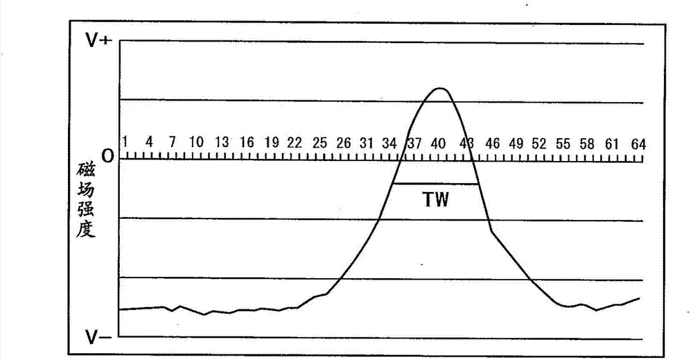
[0047] Example 1 Move in the X direction until the maximum magnetic field intensity curve reaches the maximum value, and then stop scanning. In fact, if Figure 6 As shown, in order to determine the maximum value, that is, to identify a decreasing tendency, further scans were performed several times. according to Figure 6 , the scan line number that produces the maximum value is 36, according to the scan line number 36 and image 3 The corresponding magnetic field strength characteristic curve is used to obtain the magnetic effective track width TW.
[0048] according to Figure 6 , the number of scanning lines in the present embodiment is 37 s...
Embodiment 2)
[0061] Figure 8 It is a diagram showing a second embodiment of limiting the scanning range within the scanning line for obtaining the magnetic effective track width TW.
[0062] The magnetic stripe 1 forms 40 to 60 magnetic heads. If multiple inspections are carried out according to the method of Example 1, then as Figure 9 As shown, the start position S and the end position E within the scan in each magnetic field intensity characteristic curve necessary for obtaining the effective track width TW can be known. Therefore, after a few scanlines, only that range is scanned. In addition, if the magnetic strips 1 are produced in the same batch, the scanning range within the scanning line can also be limited according to the results of other magnetic strips 1 produced in the same batch.
[0063] In Example 2, compared with Example 1, the scan time can be further reduced.
Embodiment 3)
[0065] Figure 10 It is a diagram showing a third embodiment in which the scanning range for obtaining the magnetically effective track width TW is further limited. Example 3 is an example in which the method of thinking of Example 2 is further developed, and the scanning range is narrowed in the same manner as in Example 2 in the flat portion in the X direction.
[0066] In embodiment 3, for two-dimensional scanning, such as Figure 9 As shown, if the start position S and the end position E in the scan are respectively set to 30 and 46, the range of the scan becomes 17, so the scan time can be reduced to For the magnetic strips 1 of the same batch, the thinking method of Embodiment 2 can also be followed.
PUM
 Abstract
Description
Claims
Application Information
 - R&D
- Intellectual Property
- Life Sciences
- Materials
- Tech Scout
- Unparalleled Data Quality
- Higher Quality Content
- 60% Fewer Hallucinations
Browse by: Latest US Patents, China's latest patents, Technical Efficacy Thesaurus, Application Domain, Technology Topic, Popular Technical Reports.
© 2025 PatSnap. All rights reserved.Legal|Privacy policy|Modern Slavery Act Transparency Statement|Sitemap|About US| Contact US: help@patsnap.com