
A kind of gate electrode and preparation method thereof

A gate electrode and gate oxide technology, applied in the field of gate electrode and its preparation, can solve the problems of large error of a single resistance, affecting the normal operation of a chip, uneven switching speed of the chip, etc.

Active Publication Date: 2015-11-11
ZHUZHOU CRRC TIMES SEMICON CO LTD
View PDF4 Cites 0 Cited by
  • Summary
  • Abstract
  • Description
  • Claims
  • Application Information

AI Technical Summary

Problems solved by technology

When the gate resistor connected in series with the gate pad area and the gate bus bar is damaged, the signal cannot be transmitted between the gate pad area and the gate bus bar, thus affecting the normal operation of the chip and even causing damage to the entire chip
In addition, the error of a single resistor is large. When multiple chips are connected in parallel, for the same gate pad area signal between different chips, the signal on the gate bus bar is very different, which will easily lead to uneven switching speed and The technical problem of uneven flow

Method used


Image

  • A kind of gate electrode and preparation method thereof
  • A kind of gate electrode and preparation method thereof
  • A kind of gate electrode and preparation method thereof

Examples


Embodiment 1

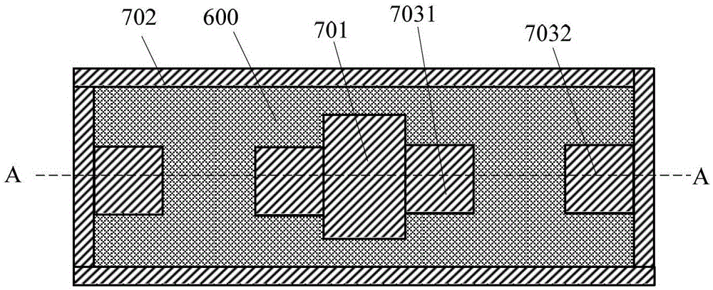
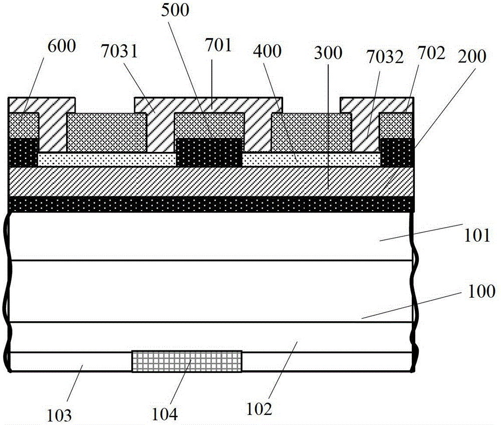
[0054] combine Figure 1 to Figure 2 The structure of the gate electrode in Embodiment 1 of the present invention will be described. figure 1 is the top view of the gate electrode, figure 2 is a cross-sectional view of the gate electrode along the direction A-A.

[0055] The gate electrode includes a substrate 100, a gate oxide layer 200 and a polysilicon layer 300 located on the substrate 100 in sequence, wherein the polysilicon layer 300 includes a first region and a second region, and the division of the first region and the second region is determined according to the layer structure above the polysilicon layer 300, and the second region includes at least a subregion surrounding the first region. It can also be understood in this way that the first area is embedded in the second area. The first region includes at least two discontinuous sub-regions.

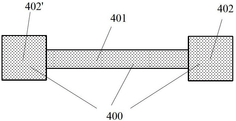
[0056] The gate electrode also includes a metal silicide layer 400 on the first region of the polysilicon layer 300 . ...

Embodiment 2

[0071] combine Figure 6 Referring to FIG. 7 ( 8 b ), the preparation method of the gate electrode provided by the embodiment of the present invention is described. The preparation method of the gate electrode comprises the following steps,

[0072] S61. Provide a substrate:

[0073] A substrate 100 is provided. Referring to FIG. 7 (1), the material of the substrate 100 can be a common silicon semiconductor material, or a wide bandgap semiconductor material such as silicon carbide, gallium nitride or diamond. The thickness range of the substrate is between 50-800 μm. The front surface of the substrate material has a first diffusion well 101, and the width of the first diffusion well is not smaller than the width of the gate electrode. The conductivity type of the first diffused well 101 is opposite to that of the substrate 100. The first diffused well is used to protect and prevent the depletion or even inversion of the gate electrode region in the reverse withstand voltag...


PUM

PropertyMeasurementUnit
thicknessaaaaaaaaaa

Abstract

The invention provides a grid electrode and a preparation method thereof. The grid electrode comprises a metal silicide layer which is formed above a first region of a polycrystalline silicon layer, wherein the metal silicide layer comprises at least two sub-regions; the metal silicide layer is used as a grid resistor of the grid electrode in function; and each sub-region of the metal silicide layer is equivalent to a branch resistor of the grid resistor. According to the grid electrode, at least two sub-regions are connected in parallel so as to achieve the purpose of forming the grid resistor by connecting a plurality of branch resistors between a main grid region and grid strips. The grid electrode can overcome the defect that an entire chip is probably damaged due to damage of the grid resistor brought by the situation that a single resistor is connected in series to a grid bonding pad region and a grid bus bar. Meanwhile, the grid electrode can improve the uniform current distribution property and the switch control characteristic between chips.

Description

technical field [0001] The invention relates to the field of semiconductor devices, in particular to a gate electrode and a preparation method thereof. Background technique [0002] Currently, only one gate resistor is provided between the gate pad area of ​​the gate electrode on the power semiconductor chip and each gate bus bar, and the gate resistor is connected in series between the gate pad area and the gate bus bar. When the gate resistor connected in series with the gate pad area and the gate bus bar is damaged, the signal cannot be transmitted between the gate pad area and the gate bus bar, thus affecting the normal operation of the chip and even causing damage to the entire chip . In addition, the error of a single resistor is large. When multiple chips are connected in parallel, for the same gate pad area signal between different chips, the signal on the gate bus bar is very different, which will easily lead to uneven switching speed and Technical problems of une...

Claims


Application Information

Patent Timeline
Patent Type & Authority Patents(China)
IPC IPC(8): H01L21/336H01L29/49H01L29/78H01L21/283
Inventor 刘国友覃荣震黄建伟罗海辉
Owner ZHUZHOU CRRC TIMES SEMICON CO LTD
Learn More