Substation video monitoring system based on SIP protocol and video transmission method

A technology of video surveillance system and SIP protocol, which is applied in closed-circuit television system, pulse modulation television signal transmission, transmission system and other directions, can solve the problem that the lean management and intensive management of video surveillance system cannot be effectively supported, and the technical performance indicators are uneven. Different, unable to centralize monitoring and other problems to achieve consistency and immediacy, and meet the effect of globalization

Inactive Publication Date: 2013-10-23
四川省电力公司通信自动化中心
View PDF4 Cites 6 Cited by
  • Summary
  • Abstract
  • Description
  • Claims
  • Application Information

AI Technical Summary

Problems solved by technology

[0003] The substation video monitoring system in the existing power system is constructed by different departments in different periods and with different projects, and the systems and equipment of different equipment manufacturers and different periods are used, forming the current product models with many types and technical performance indicators The status quo is uneven and cannot be unified and centralized monitoring
It not only fails to meet the requirements of unattended substations, but also fails to meet the development needs of the intelligent construction of the power grid, which seriously affects the intelligent improvement of the video surveillance system, and cannot effectively utilize the technology of the video surveillance system in the lean management and intensive management of the company support
Therefore, unified construction standards, unified technical system and unified platform management to meet the global and integrated development needs of video surveillance systems have become the key technology to solve the interconnection of video surveillance systems from various manufacturers. At present, there are no literature reports and Applications

Method used


Image

  • Substation video monitoring system based on SIP protocol and video transmission method

Examples


Embodiment Construction

[0018] The present invention will be further described below in conjunction with accompanying drawing:

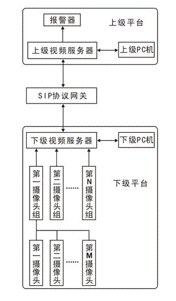
[0019] As shown in the accompanying drawings, the substation video monitoring system based on the SIP protocol of the present invention includes a lower-level platform, a higher-level platform and a SIP protocol gateway, and the lower-level platform includes a lower-level video server, a lower-level PC, and a plurality of camera groups, the camera in the figure The group includes the first camera group, the second camera group, ..., the Nth camera group, and each camera group includes a plurality of cameras, and the cameras in the figure include the first camera, the second camera, ..., the M camera, and the multiple cameras are respectively It is installed at the monitoring position of the substation. The upper-level platform includes the upper-level video server, the upper-level PC and the alarm. The signal output terminals of multiple camera groups are respectively connec...


PUM


Abstract

The invention discloses a substation video monitoring system based on an SIP protocol. A plurality of camera groups are respectively connected with a lower video server which is connected with a lower PC machine. The lower video server is connected with an upper video server through an SIP protocol gateway. The upper video server is respectively connected with an alarm device and an upper PC machine. The invention also discloses a video transmission method which comprises the following steps: a lower platform registers to an upper platform; the lower platform sends a NOTIFY message to the lower platform and informs an event to the upper platform; the lower platform pushes monitoring region information and monitoring scene information in an XML message body orderly to the upper platform; camera information is pushed; and the upper platform sends '200' to the lower platform, which indicates that the pushing of the information is completed. According to the system and the method, the video monitoring information collected by a camera is subjected to grading management and the real-time information transmission is realized through the SIP gateway between an upper level and a lower level, and the purpose of sharing information is achieved.

Description

technical field [0001] The invention relates to a substation video monitoring system and a video transmission method, in particular to a substation video monitoring system and a video transmission method based on the SIP protocol for hierarchical management and information sharing between upper and lower levels. [0002] Background technique [0003] The substation video surveillance system in the existing power system is constructed by different departments in different periods and with different projects, and the systems and equipment of different equipment manufacturers and different periods are used, forming the current product models with many types and technical performance indicators. Uneven, unable to unify the status quo of centralized monitoring. Not only can it not meet the requirements of unattended substations, but also can not meet the development needs of the intelligent construction of the power grid, which seriously affects the intelligent improvement of t...

Claims


Application Information

Patent Timeline
Patent Type & Authority Applications(China)
IPC IPC(8): H04N7/18H04N7/24H04L29/06
Inventor 李富祥马玫卫小凡杨鸿昌徐亮彭伟夫王炜杜书唐娜
Owner 四川省电力公司通信自动化中心
Why Eureka
Try Eureka