
Automatic pin supply equipment

A technology of supplying equipment and needle insertion, which is applied in the field of automatic needle supply equipment for injection molding, which can solve the problems of long operation period of the equipment, cumbersome needle removal process, and inaccurate positioning of the front needle, so as to achieve safe and reliable equipment efficiency, reduce The effect of improving the number of personnel used and equipment efficiency

Active Publication Date: 2016-01-27
JINHUA CALET AUTOMATION TECH
View PDF7 Cites 0 Cited by
  • Summary
  • Abstract
  • Description
  • Claims
  • Application Information

AI Technical Summary

Problems solved by technology

[0005] 1. The needle extraction process of the equipment is cumbersome, resulting in a long period of equipment action process;
[0006] 2. The needle cannot be accurately positioned before the needle taking manipulator picks up the needle, resulting in the phenomenon of missed or dropped needles when the needle taking manipulator picks up the needle;

Method used


Image

  • Automatic pin supply equipment
  • Automatic pin supply equipment
  • Automatic pin supply equipment

Examples


Embodiment Construction

[0041] In order to understand the above-mentioned purpose, features and advantages of the present invention more clearly, the present invention will be further described in detail below in conjunction with the accompanying drawings and specific embodiments. It should be noted that, in the case of no conflict, the embodiments of the present application and the features in the embodiments can be combined with each other.

[0042] In the following description, many specific details are set forth in order to fully understand the present invention. However, the present invention can also be implemented in other ways than described here. Therefore, the protection scope of the present invention is not limited by the specific implementation disclosed below. Example limitations.

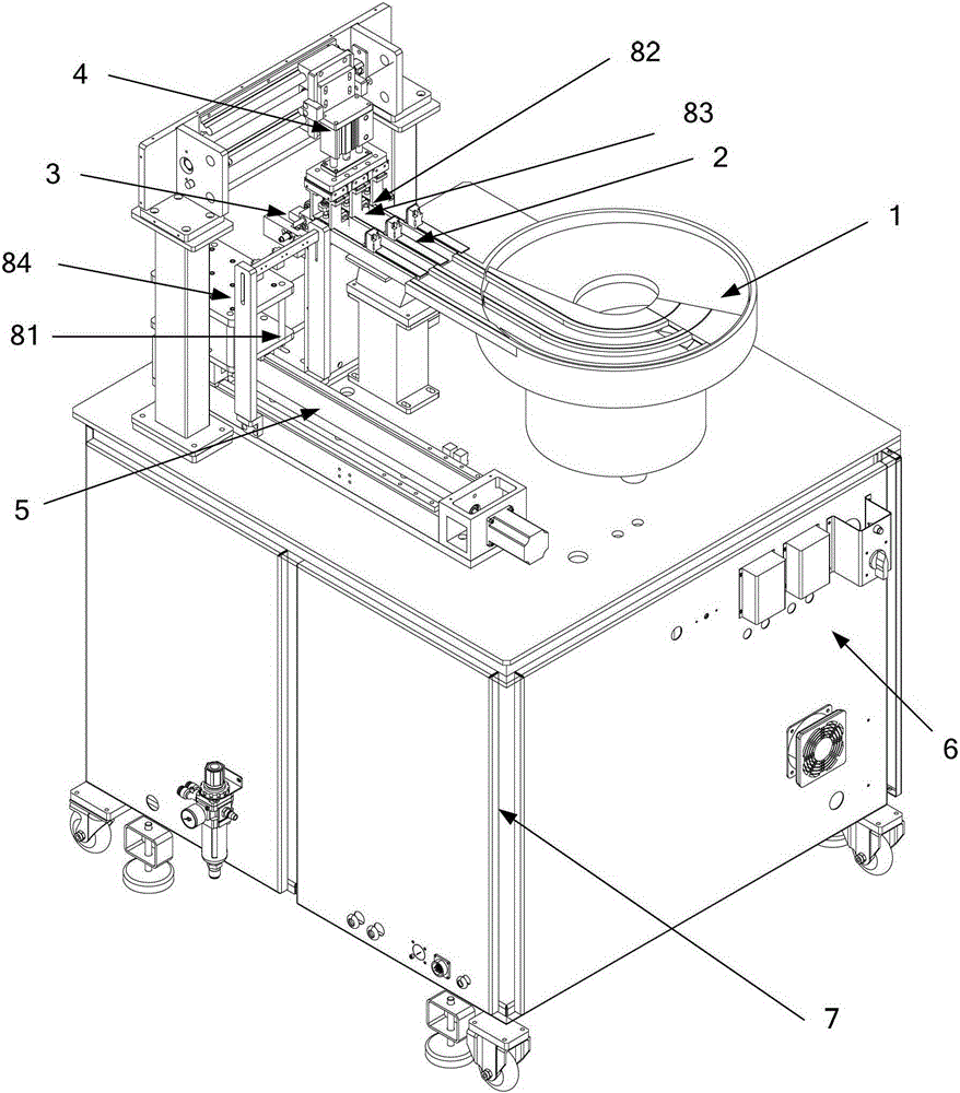
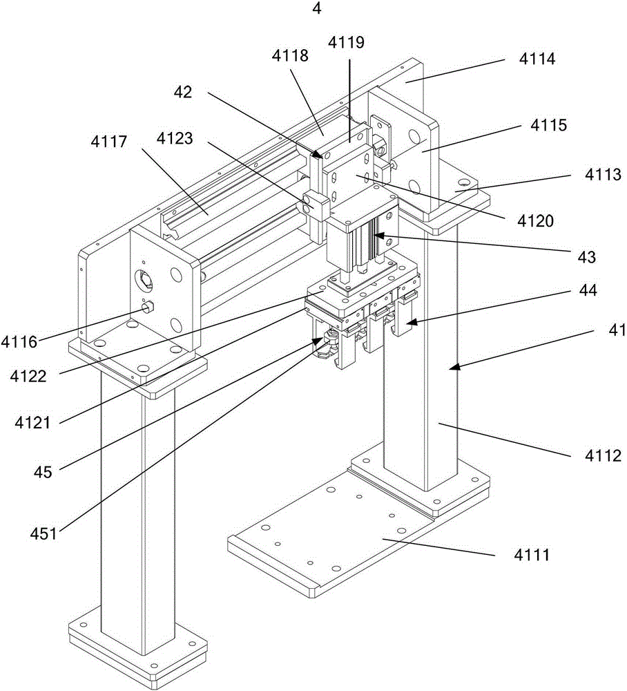
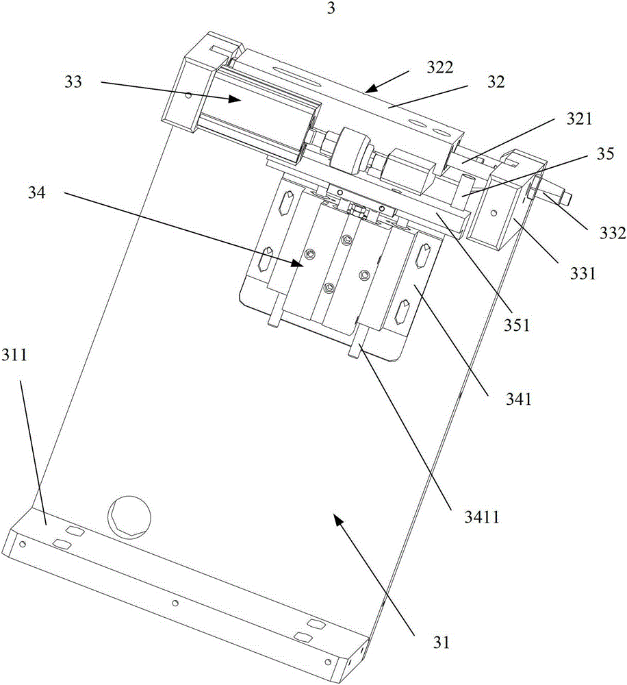
[0043] The automatic pin supply equipment provided by the present invention, such as figure 1 As shown, it includes a needle storage device 1, a needle transport device 2, a needle ejector device 3, a needle...


PUM


Abstract

The invention provides automatic insert pin supply equipment which comprises a pin storage device, a pin conveying device, a pin jacking device, a pin taking device, a pin collecting device and a control system; the pin storage device is connected with one end of the pin conveying device; the pin jacking device is arranged at the other end of the pin conveying device; the pin taking device is located above the pin jacking device; the pin collecting device is located below the pin taking device; the control system is connected with and controls pin storage device, the pin conveying device, the pin jacking device, the pin taking device and the pin collecting device. The automatic insert pin supply equipment has the advantages that the degree of automation of the equipment can be improved; the pin taking action and the correction action are combined to achieve the purposes of reducing the times of pin taking, shortening the action cycle of the equipment and improving the recovery rate of the equipment; inserted pins are loaded into the module of an injection machine with the aid of a mechanical hand, no worker is needed in the whole process, the equipment has high efficiency and is safe and reliable.

Description

technical field [0001] The invention relates to the technical field of injection molding industry, in particular to an automatic pin supply equipment for injection molding. Background technique [0002] With the development of the injection molding industry, peripheral material supply is going through a stage of development from semi-automated to fully automated. Although there are currently automated pin insertion machines to insert the pins, these devices have a long cycle of pin insertion, and operators need to be equipped to check whether the pin insertion holes are completely filled with pins, and the number of rows of pins is also limited to one row. At the same time, it is necessary to manually replace the mold, resulting in low efficiency of the equipment. [0003] The prior art discloses a PCB board needle insertion machine, after the ejector device installed on it ejects the needles on the needle moving block, the ejected needles are moved to the correction board ...

Claims


Application Information

Patent Timeline
Patent Type & Authority Patents(China)
IPC IPC(8): H05K3/30
Inventor 徐锦波
Owner JINHUA CALET AUTOMATION TECH
Learn More