
Wheel rotor

A technology for wheel loaders and work machines, which is applied in the direction of control mechanism, mechanical control device, earth mover/shovel, etc. to achieve the effect of good operability

Active Publication Date: 2013-10-23
HITACHI CONSTR MASCH CO LTD
View PDF6 Cites 6 Cited by
  • Summary
  • Abstract
  • Description
  • Claims
  • Application Information

AI Technical Summary

Problems solved by technology

[0009] Therefore, compared with the operation instruction of (B), the operation instruction of (C) requires delicate operation and needs to be carried out intensively, so many operators tend to hold the bucket operation lever tightly and operate

Method used


Image

  • Wheel rotor
  • Wheel rotor
  • Wheel rotor

Examples


Embodiment Construction

[0026] Embodiments of the present invention will be described below using the drawings.

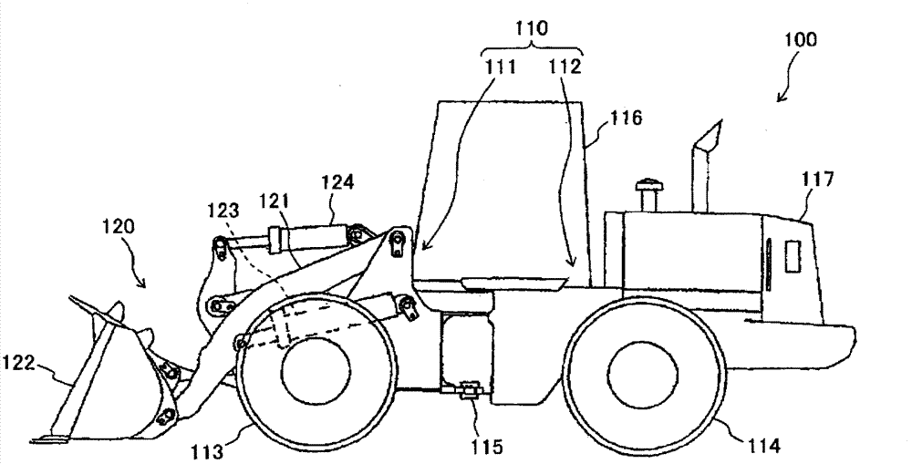
[0027] figure 1 It is a side view of the wheel loader according to one embodiment of the present invention.

[0028] figure 1 The illustrated wheel loader 100 includes a vehicle body 110 and a working machine 120 attached to the front of the vehicle body 110 .

[0029] The vehicle body 110 includes a front body 111 and a rear body 112 . The front body 111 and the rear body 112 have front wheels (tyres) 113 and rear wheels (tyres) 114 respectively, and are connected to each other in a bendable manner via a center pin 115 extending in the vertical direction. Although not shown in the figure, a steering cylinder is connected to the front body 111 and the rear body 112 , and the front body 111 bends left and right with respect to the rear body 112 as the steering cylinder is telescopically driven. In addition, a cab 116 is mounted on the front portion of the rear body 112 , and an engine ...


PUM


Abstract

This wheel rotor (100) is provided with: a vehicle body (110) having wheels (113, 114); a work machine (120) having an arm (121) attached to the anterior section of the vehicle body (110), a bucket (122), an arm cylinder (123) that drives the bucket (122) and the arm (121), and a bucket cylinder (124); and a work machine operation device (20) that designates the operation of the work machine (120). The work machine operation device (20) is provided with: an arm operation lever (11) for operating the arm and provided to the right side of a driving seat (21); and two kickdown switches respectively provided to the top surface and left side surface of the grip (11a) of the arm operation lever (11). As a result, it is possible to further increase operability.

Description

technical field [0001] The present invention relates to a wheel loader for excavating and transporting objects to be excavated. Background technique [0002] A work machine of a wheel loader generally has an arm cylinder for pitching the arm and a bucket cylinder for dumping or shoveling the bucket. An operating device for instructing actions, for example, has two operating levers for arm operation and bucket operation (hereinafter respectively referred to as "arm operating lever" and "bucket operating lever") on the right-hand side of the driver's seat. (Refer to Patent Document 1 and the like). [0003] Patent Document 1: International Publication No. WO2010 / 147232 [0004] Here, as a typical operation of the wheel loader, (A) moves to the vicinity of a pile of objects to be excavated such as sand (hereinafter, appropriately referred to as "pile"), and (B) directs the mouth of the bucket toward The front is inserted into the pile with the arm lowered, and (C) advances f...

Claims


Application Information

Patent Timeline
IPC IPC(8): E02F9/20E02F3/34E02F9/02
CPCE02F9/2221E02F3/283E02F9/2004G05G9/047E02F9/2012E02F3/431E02F9/2066E02F9/2079E02F9/2253E02F3/34E02F9/02E02F9/20
Inventor 兵藤幸次吉川正规高桥咏井坂涉
Owner HITACHI CONSTR MASCH CO LTD
Features
  • Generate Ideas
  • Intellectual Property
  • Life Sciences
  • Materials
  • Tech Scout
  • Unparalleled Data Quality
  • Higher Quality Content
  • 60% Fewer Hallucinations
Learn More