Locking and lifting mechanism for reactor fuel assembly and locking and lifting method

A fuel assembly and reactor technology, applied in the direction of reactor fuel elements, reactors, greenhouse gas reduction, etc., can solve the problem that it is difficult to withstand the high temperature of liquid lead-bismuth coolant, high corrosion and high radiation environment, and the comprehensive effect of seismic load, etc., to achieve complex structure The effect of reduced sex, good operability, and easy operation

Active Publication Date: 2018-05-15
INST OF MODERN PHYSICS CHINESE ACADEMY OF SCI
View PDF6 Cites 7 Cited by
  • Summary
  • Abstract
  • Description
  • Claims
  • Application Information

AI Technical Summary

Problems solved by technology

[0008] As mentioned above, the existing locking schemes for reactor fuel assemblies are difficult to withstand the combined effects of hig

Method used


Image

  • Locking and lifting mechanism for reactor fuel assembly and locking and lifting method
  • Locking and lifting mechanism for reactor fuel assembly and locking and lifting method
  • Locking and lifting mechanism for reactor fuel assembly and locking and lifting method

Examples


Embodiment Construction

[0030] Exemplary embodiments of the present invention are described in detail below with reference to the accompanying drawings.

[0031] 【The overall structure】

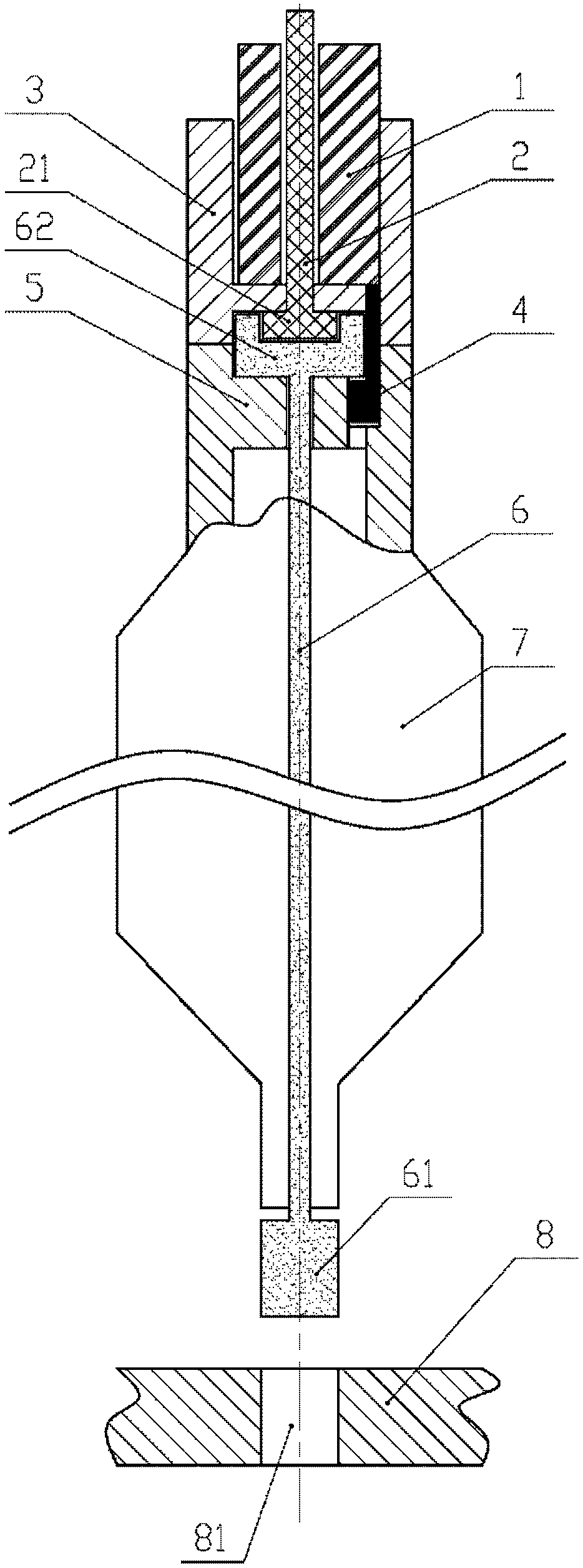
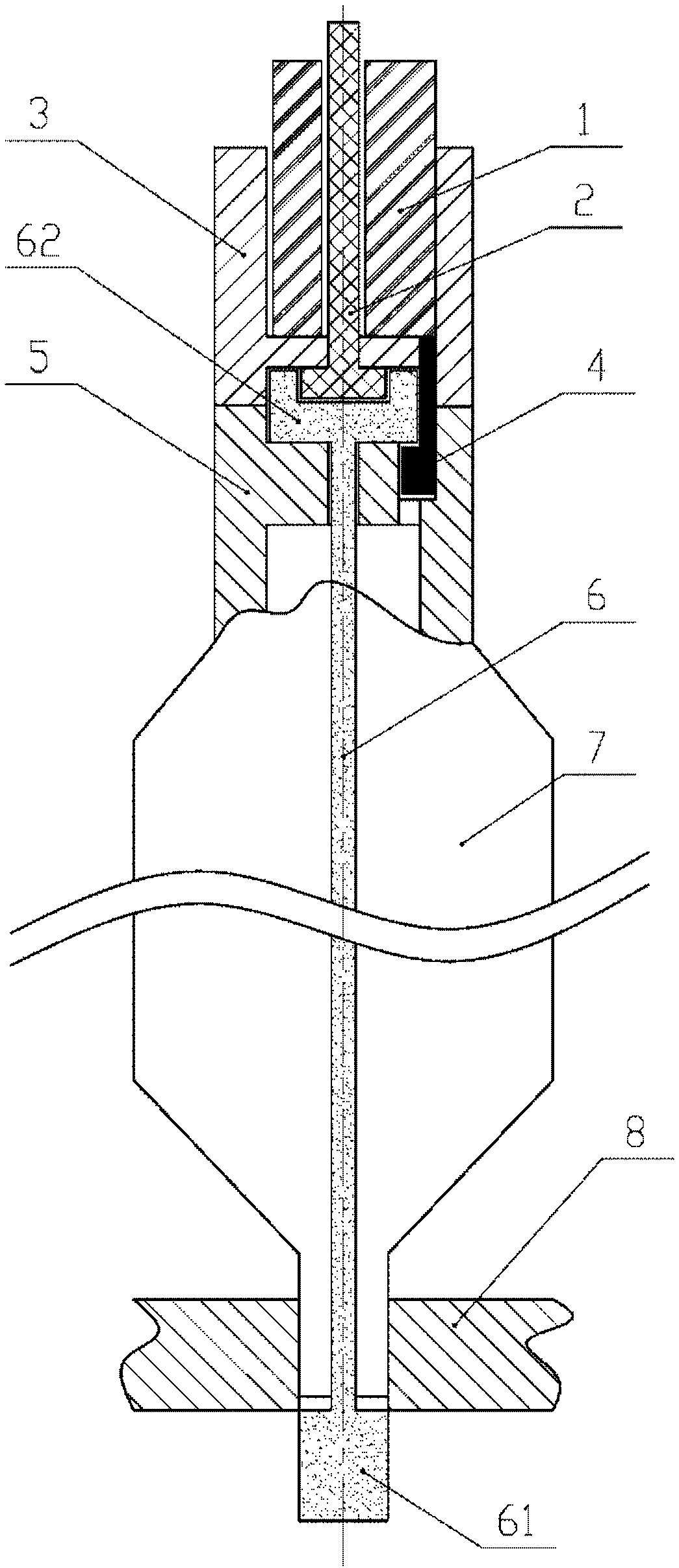
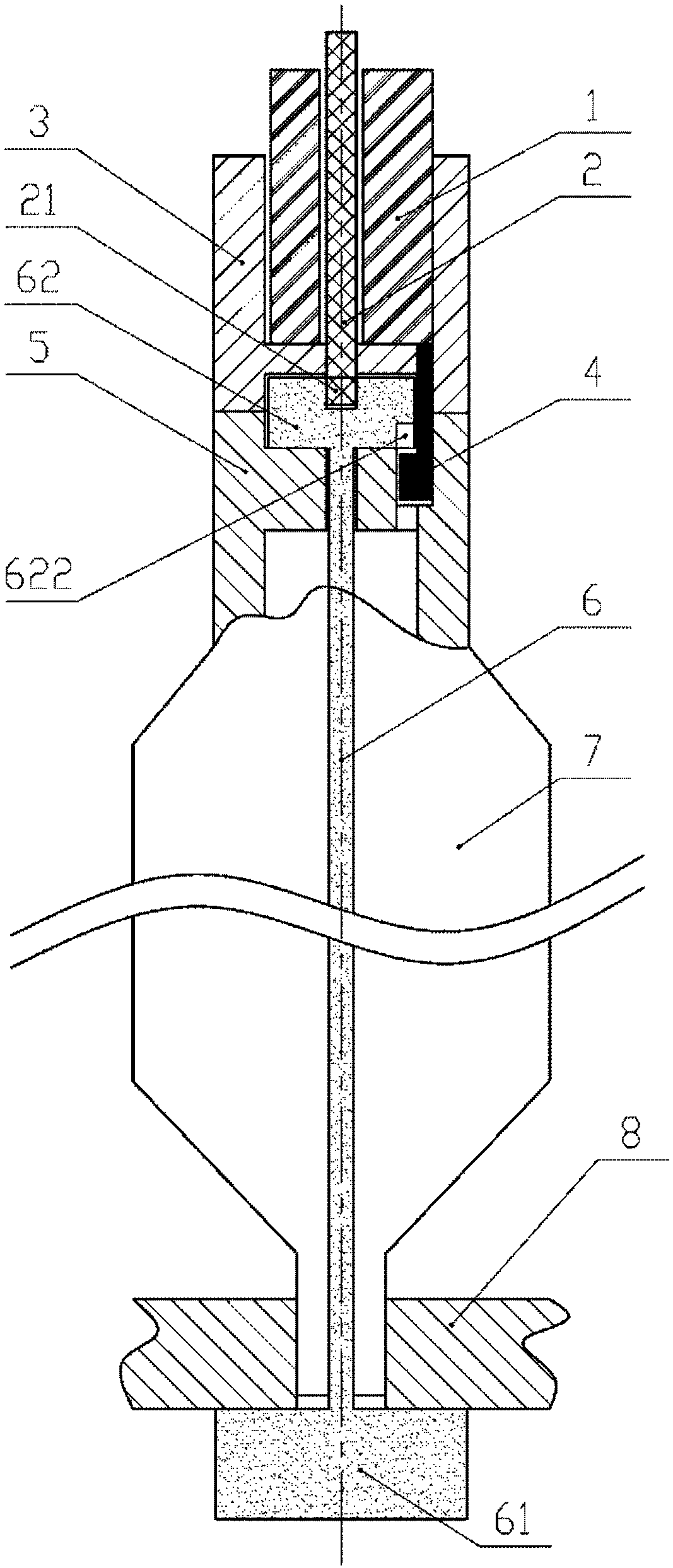
[0032] refer to figure 1 , image 3 , Figure 4 and Figure 5 , an exemplary locking and lifting mechanism according to an embodiment of the present invention includes a guide shaft 1 , a rotary claw 2 , an operating head 3 , a buoyancy pin 4 , a positioning sleeve 5 , a locking rod 6 and a lower grid plate 8 .

[0033] Specifically, the guide shaft 1 can move up and down in the vertical direction. The rotary claw 2 runs through the guide shaft 1 in the vertical direction, can move up and down together with the guide shaft 1, and can rotate around its own vertical axis. The operating head 3 has a cavity for accommodating the guide shaft 1 and the claw 2 . The bottom of the operating head 3 is provided with a through hole 31 . The through hole 31 has a shape matched with the shape of the lower end lock head 21...


PUM


Abstract

The invention discloses a locking and lifting mechanism for a reactor fuel assembly and an operation method thereof. The mechanism comprises a rotating claw, an operation head, a positioning shaft sleeve, a locking rod and a lower grid plate, wherein the rotating claw can move and rotate around a vertical axis; the operation head can be locked together or separated from the rotating claw; the positioning shaft sleeve fixedly connects the operation head together with the fuel assembly; the locking rod runs through the positioning shaft sleeve and the fuel assembly, and can rotate around the vertical axis; a lower-end locking head of the locking rod extends out of the lower end of the fuel assembly; the lower grid plate is fixed at the bottom of a reactor. In an initial state, the rotating claw is locked together with the operation head, and the locking rod is not locked together with the lower grid plate. After the reactor fuel assembly is arranged in place on the lower grid plate, therotating claw is unlocked from the operation head by being rotated by an angle to allow the rotating claw to be separated from the operation head; meanwhile, the lower-end locking head of the lockingrod is locked together with the lower grid plate by being rotated by an angle under the driving action of the rotating claw, so that the fuel assembly is locked on the lower grid plate.

Description

technical field [0001] The invention relates to a locking and lifting mechanism and a locking and lifting method of a reactor fuel assembly, and more particularly to a locking and lifting mechanism and a locking and lifting method for an accelerator-driven subcritical reactor fuel assembly in the field of nuclear energy utilization. Background technique [0002] The accelerator driven sub-critical system (Accelerator Driven Sub-critical System, hereinafter referred to as ADS) is mainly composed of an accelerator, a heavy nuclear spallation target and a subcritical reactor. The principle of this system is: use the high-energy and strong-current proton beam generated by the accelerator to bombard the heavy nuclear spallation target, generate wide-energy spectrum, medium-high flux neutrons, and use this as an external source to drive the fissile material in the subcritical reactor A continuous chain reaction that eventually converts long-lived, highly reflective nuclides into n...

Claims


Application Information

Patent Timeline
IPC IPC(8): G21C19/105G21C19/11G21C19/20
CPCG21C19/105G21C19/11G21C19/20Y02E30/30
Inventor 朱彦雷顾龙于锐蔡义林彭天骥王大伟李金阳秦长平刘璐盛鑫唐延泽张璐田旺盛冯丽
Owner INST OF MODERN PHYSICS CHINESE ACADEMY OF SCI
Why Eureka
Try Eureka