Method for the autonomous localization of a driverless, motorized vehicle

An unmanned driving and vehicle technology, applied in the direction of motor vehicles, vehicle position/route/height control, two-dimensional position/channel control, etc., can solve the problems of vehicle parking and vehicle positioning, and achieve measurement data density Improved effect

Active Publication Date: 2013-10-23
SIEMENS AG
View PDF8 Cites 15 Cited by
  • Summary
  • Abstract
  • Description
  • Claims
  • Application Information

AI Technical Summary

Problems solved by technology

Conversely, in areas with only a few landmarks, no landmarks are detected

Method used


Image

  • Method for the autonomous localization of a driverless, motorized vehicle
  • Method for the autonomous localization of a driverless, motorized vehicle
  • Method for the autonomous localization of a driverless, motorized vehicle

Examples


Embodiment Construction

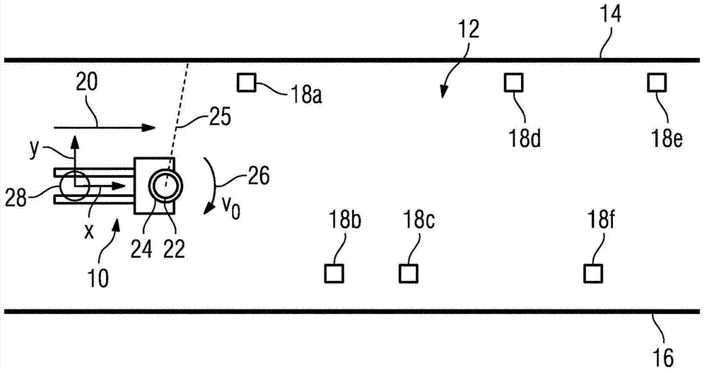
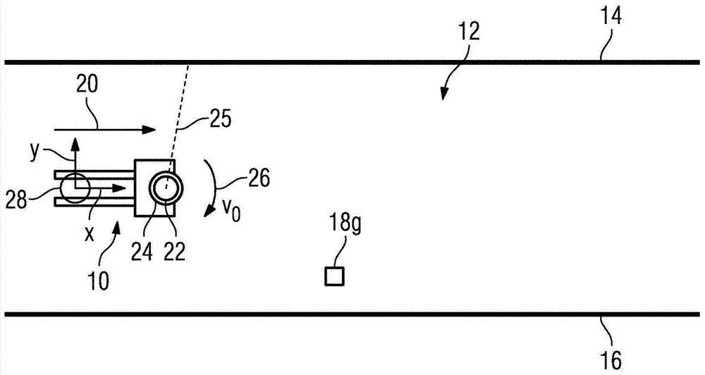
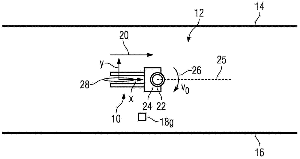
[0019] figure 1 Shown is a schematic plan view of an unmanned motorized vehicle 10 , which is positioned using an autonomous localization method within a known environment 12 , which is delimited here by two walls 14 and 16 arranged opposite one another. . Vehicle 10 is positioned by means of natural landmarks in the form of walls 14 and 16 as well as existing geometrical structures 18 a, b, c, d, e, f in environment 12 , such as pipes, beams, columns or the like. When vehicle 10 is moving in the direction of movement indicated by arrow 20 , these natural landmarks 14 , 16 , 18 a to f are detected by means of a distance-measuring sensor 22 arranged on vehicle 10 , which is a laser scanner. The sensor 22 is arranged on a sensor motor 24 such that its measuring plane 25 can be pivoted about a pivot axis (not shown in detail) by the drive 24 of the sensor motor. By deflecting the sensor 22 , as indicated by the arrow 26 , the environment 12 can correspondingly be scanned three-...


PUM


Abstract

A map of area is created based on natural landmarks (14,16), and the preset route along which the vehicle (10) is to move is set. The landmarks that serve as a route along preset location is determined, and the environment (12) is scanned at different times using a sensor (22) for detecting the preset landmarks while the vehicle moves along preset route. The vehicle is located by comparing the detected landmarks with destination shown on map landmarks. The speed and/or direction of rotation of sensor motor (24) are controlled such that sensor is aligned on few preset landmarks.

Description

technical field [0001] The invention relates to a method for autonomous localization of an unmanned motorized vehicle within a known environment using at least one sensor. Background technique [0002] Such methods are known in various designs from the prior art. It is used to determine the position of an unmanned motorized vehicle, thereby enabling unmanned navigation of the vehicle. [0003] Such positioning methods are used, for example, in the field of warehouse logistics. There, unmanned motorized vehicles are increasingly used for the transport of goods in order to achieve a high degree of automation. [0004] Existing positioning methods use additional so-called artificial landmarks in the form of installations such as reflector markers, wires, radio stations or the like. These artificial landmarks are placed within the known environment within which the vehicle should be localized, which on the one hand provides enough landmarks for a reliable localization, but on...

Claims


Application Information

Patent Timeline
IPC IPC(8): G05D1/02G01S17/86
CPCG05D1/024G05D2201/0216G05D1/0274G01S17/86
Inventor 梅尔滕·利普科夫斯基托马斯·韦斯奇
Owner SIEMENS AG
Why Eureka
Try Eureka