A nitrogen-free circulation heating device for partial oxidation system

An oxidation system and heating device technology, applied in the preparation of organic compounds, inorganic chemistry, organic chemistry, etc., can solve the problems of energy waste and output reduction, and achieve the effects of increasing output, eliminating waste, and saving energy

Inactive Publication Date: 2017-06-16
CHINA COAL ENERGY HEILONGJIANG COAL CHEM
View PDF6 Cites 0 Cited by
  • Summary
  • Abstract
  • Description
  • Claims
  • Application Information

AI Technical Summary

Problems solved by technology

[0005] In order to solve the problems of energy waste and output reduction caused by parking during the heating process of the existing methanol production device in the partial oxidation process, the present invention further proposes a non-circulating nitrogen heating scheme for the partial oxidation system

Method used


Image

  • A nitrogen-free circulation heating device for partial oxidation system

Examples


specific Embodiment approach 1

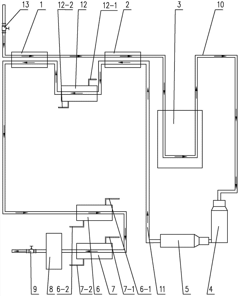
[0013] Specific implementation mode one: combine figure 1 To illustrate, a nitrogen non-circulation heating device for partial oxidation system described in this embodiment includes a feed gas preheater 1, a mixed gas preheater 2, a heating furnace 3, a reformer 4, a waste heat boiler 5, and a desalinated water preheater. Heater 6, water cooler 7, separator 8, vent valve 9 and boiler feed water preheater 12, the nitrogen delivery pipe passes through the first connecting pipe 10 from front to back through the feed gas preheater 1, the mixed gas preheater 2, the heating furnace 3 and the reformer 4, the exhaust end of the reformer 4 is connected to the waste heat boiler 5, the exhaust end of the waste heat boiler 5 is connected to the second connecting pipe 11, and the second connecting pipe 11 passes through from front to back in sequence Overmixed gas preheater 2, boiler feed water preheater 12, raw gas preheater 1, desalted water preheater 6 and water cooler 7, the exhaust en...

specific Embodiment approach 2

[0023] Specific implementation mode two: combination figure 1 To illustrate, a regulating valve 13 is provided at the starting end of the first connecting pipeline 10 in this embodiment. Other compositions and connection methods are the same as those in Embodiment 1.

[0024] Such a design can adjust the speed of nitrogen gas entry at any time according to needs.

specific Embodiment approach 3

[0025] Specific implementation mode three: combination figure 1 Note that the upper end of the water cooler 7 in this embodiment is connected with a first condensate outlet pipe 7-1, and the lower end of the water cooler 7 is connected with a first condensate inlet pipe 7-2. Other compositions and connection methods are the same as those in the second embodiment.

[0026] Such a design can realize rapid cooling of nitrogen.

[0027] Specific implementation mode four: combination figure 1 Note that the upper end of the desalted water preheater 6 in this embodiment is connected with a second condensate outlet pipe 6-1, and the lower end of the desalinated water preheater 6 is connected with a second condensate inlet pipe 6-2. Other compositions and connection modes are the same as those in Embodiment 1, 2 or 3.

[0028] Such a design can realize rapid cooling of nitrogen.

[0029] Specific implementation mode five: combination figure 1 Note that the upper end of the boiler ...


PUM


Abstract

A nitrogen non-circulation heating device for partial oxidation system. The invention relates to a heating device, in particular to a nitrogen non-circulation heating device used in a partial oxidation system. The invention aims to solve the problems of energy waste and output reduction caused by shutdown during the heating process of the partial oxidation process of the existing methanol production device. A nitrogen gas delivery pipeline used in a nitrogen non-circulation heating device for a partial oxidation system passes through a first connecting pipeline from front to back through a raw material gas preheater, a mixed gas preheater, a heating furnace and a reformer, and the reformer The exhaust end of the waste heat boiler is connected to a waste heat boiler, and the exhaust end of the waste heat boiler is connected to a second connecting pipe. The second connecting pipe passes through the mixed gas preheater, the boiler feed water preheater, and the raw gas preheater in sequence from front to back. , Desalted water preheater and water cooler, the exhaust end of the water cooler is connected to the separator, and the exhaust end of the separator is provided with a vent valve. The present invention is used for nitrogen heating.

Description

technical field [0001] The invention relates to a heating device, in particular to a nitrogen non-circulation heating device used in a partial oxidation system. Background technique [0002] The methanol production unit adds a partial oxidation process after the desulfurization process and before the compression process. Its function is to convert part of the methane in the clean gas into carbon monoxide and hydrogen, so as to increase the content of active components in the methanol synthesis reaction raw material gas, thereby increasing methanol production. According to the process requirements, before the raw material gas is partially oxidized, the outlet temperature of the reformer needs to be raised to 550°C. The medium used in the temperature rise process is nitrogen, and the temperature of the reformer is raised by heating the nitrogen. The temperature rise process is called nitrogen temperature rise. [0003] The original heating technical scheme is to stop the steam...

Claims


Application Information

Patent Timeline
Patent Type & Authority Patents(China)
IPC IPC(8): C07C31/04C07C29/152C01B3/36
CPCY02P20/129
Inventor 曹立军
Owner CHINA COAL ENERGY HEILONGJIANG COAL CHEM
Why Eureka
Try Eureka