Rotary Cutters for Lawn Mowers

A rotary cutting and lawn mower technology, applied in cutters, harvesters, applications, etc., can solve the problems of removal, inability to cooperate, and deterioration of the weight balance of the head body, so as to avoid the effect of reducing efficiency

Active Publication Date: 2016-09-07
STARTING IND CO LTD
View PDF6 Cites 0 Cited by
  • Summary
  • Abstract
  • Description
  • Claims
  • Application Information

AI Technical Summary

Problems solved by technology

[0010] (1): Because the diameter of the cord guide hole defined in the head main body and the diameter of the cord perforation formed in the pressure member are determined, it cannot cooperate with cords having different thicknesses (diameters)
[0011] (2): Time and effort required increase because attaching the cord to or removing the cord from the head body requires moving the pressure member to align its cord perforation with the cord guide hole
[0012] (3): Since a U-shaped pressure member is combined at one side of the head body, the weight balance of the head body deteriorates, and vibration may be caused
[0013] (4): Since the cutting cord is held at the cord perforation of the pressure member, the holding force of the cutting cord may be insufficient, and the cutting cord may be moved or even removed from the head body due to the centrifugal force during the mowing operation

Method used


Image

  • Rotary Cutters for Lawn Mowers
  • Rotary Cutters for Lawn Mowers
  • Rotary Cutters for Lawn Mowers

Examples


no. 1 example

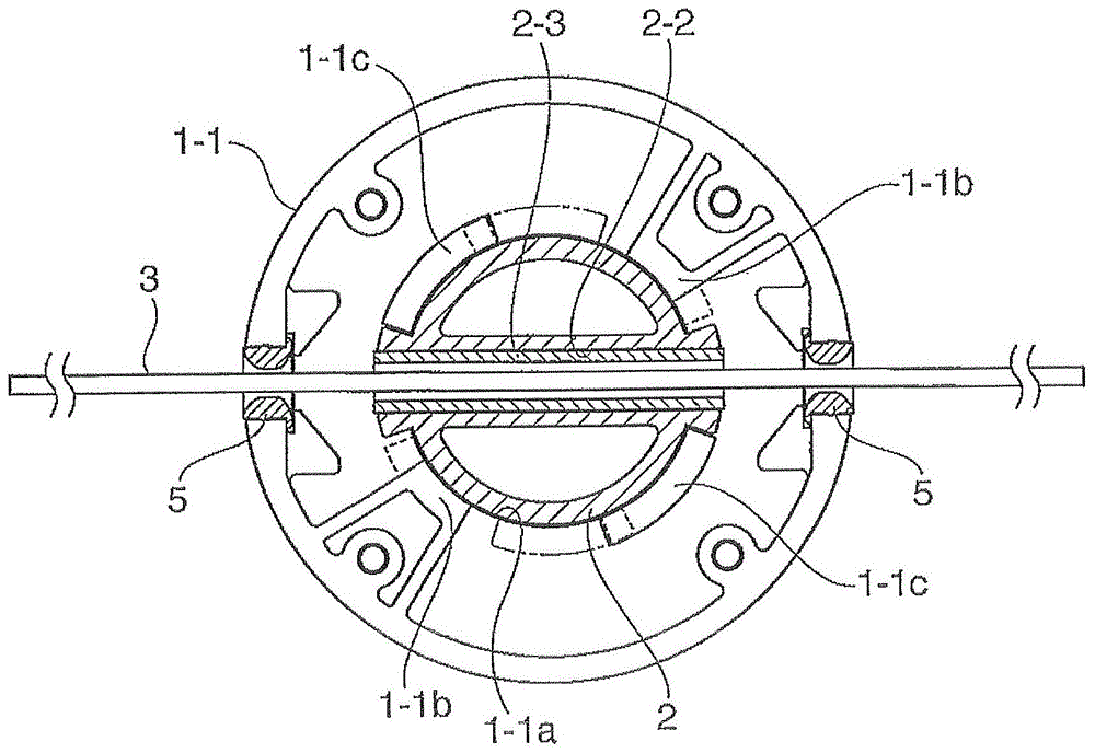
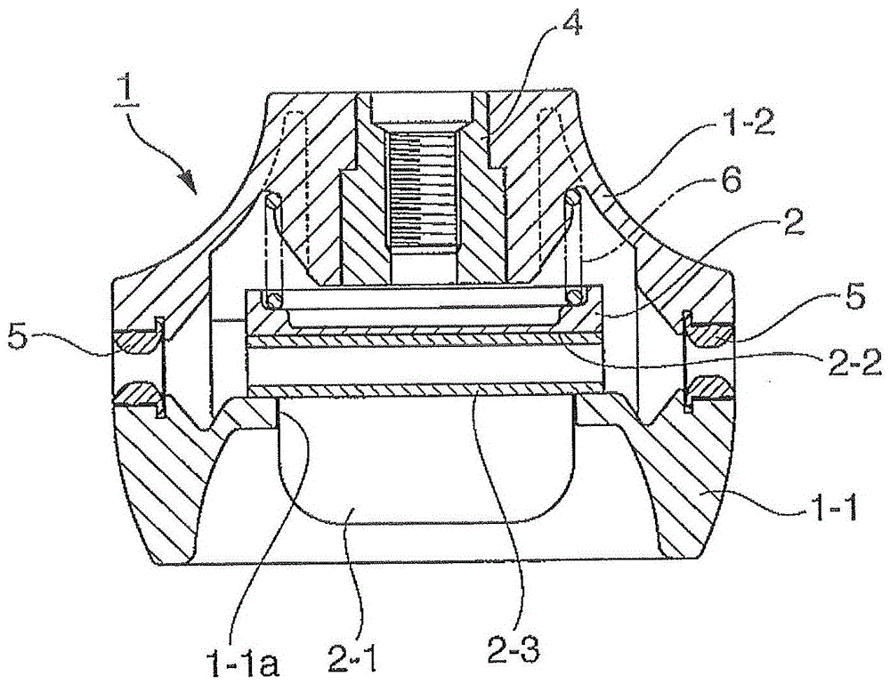
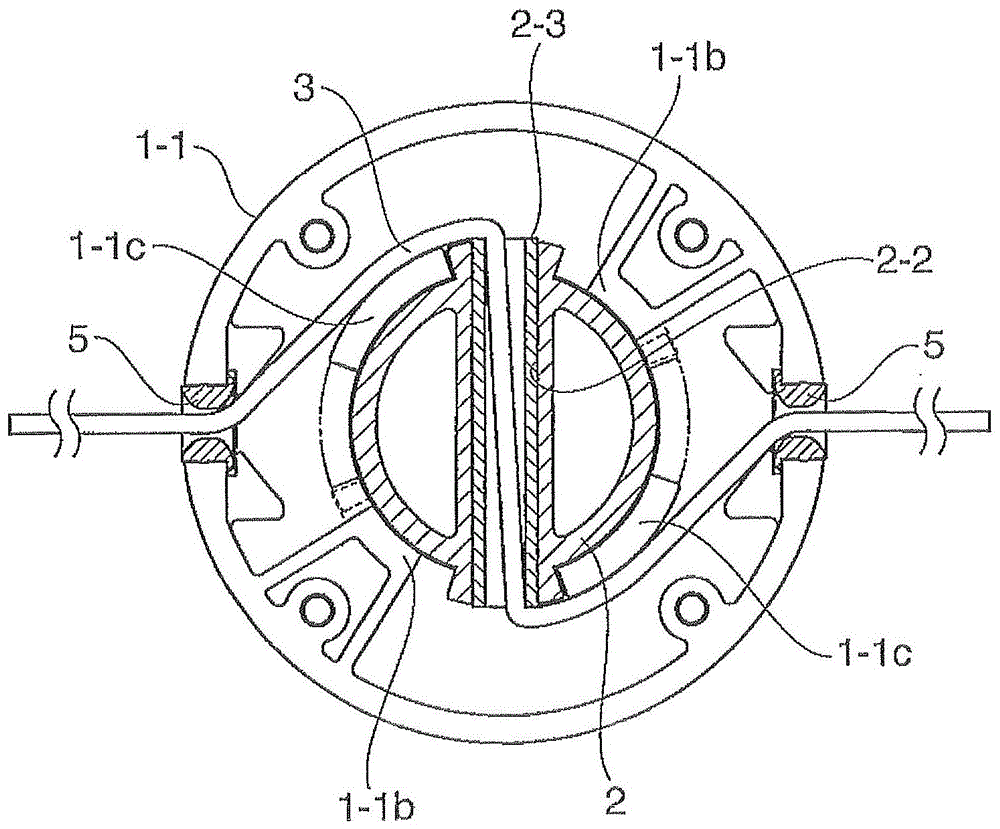
[0035] First, refer to figure 1 A rotary cutter for a lawnmower according to a first embodiment (pressure member pushing type) is described through FIG. 4 . In the rotary cutter of the first embodiment, attachment and removal of the cutting cord 3 are performed while pushing the pressure member. In this rotary cutter, a head main body 1 is composed of a housing 1-1 and a cover 1-2, and a pressure member 2 is interposed between the housing 1-1 and the cover 1-2. The pressure member 2 has a bottom cylindrical body, a flat sheet-shaped clamping portion 2-1 formed at the center of the bottom portion of the body, and a string insertion guide hole 2-2 formed at an open side of the body. The size of the string insertion guide hole 2-2 is larger than the thickness (diameter) of the cutting string 3, and extends parallel to the flat sheet-shaped clamping portion 2-1 in the radial direction. The rope support pipe 2-3 is fitted inside the guide hole 2-2. For example, the rope support ...

no. 2 example

[0047] Next, refer to Figure 5 to Figure 7 A rotary cutter for a lawnmower according to a second embodiment (pressure member pulling type) will be described. In the rotary cutter of the second embodiment, attachment and removal of the cutting cord 13 is performed while pulling the pressure member. In the rotary cutter, a head main body 11 is composed of a housing 11-1 and a cover 11-2, and a pressure member 12 is interposed between the housing 11-1 and the cover 11-2. The pressure member 12 comprises a bottomed and flanged cylindrical body. The main body of the pressure member 12 is longer than that of the pressure member 2 of the first embodiment. The pressure member 12 also includes a flat sheet-shaped clamping portion 12-1 formed at the center of the bottom portion of the main body and a cord insertion guide hole 12-2 formed close to an upper portion of the clamping portion 12-1. The size of the cord insertion guide hole 12-2 is larger than the thickness (diameter) of t...


PUM


Abstract

One embodiment of the present invention provides a rotary cutter for a lawnmower, including: a head body having a cord guide hole; and a pressure member having a cord insertion guide hole, the The cord insertion guide hole is formed to radially penetrate the pressure member. The pressure member is operable between: a first state in which the cord insertion guide hole of the pressure member is aligned with the cord guide hole of the head body so that the cutting cord can be inserted into the head body; and a second state in which the pressure member is pushed into the head body from the first state; a third state in which the pressure member rotates relative to the head body from the second state, Leave the inserted cutting rope in a bent state.

Description

[0001] Cross References to Related Applications [0002] This application claims priority from Japanese Patent Application No. 2012-100381 filed on Apr. 25, 2012, the entire contents of which are incorporated herein by reference. technical field [0003] The present invention relates to a rotary cutter for a lawnmower that cuts grass etc. by rotating a head from which a cutting cord protrudes radially, and more particularly An attachment type (non-reel-winding type) rotary cutter in which a reel for winding the cutting cord is not provided but the cutting cord is directly attached to the head, and replace the cutting rope when it becomes shorter due to wear. Background technique [0004] In general, a lawnmower includes a motor, a rotary shaft connected to the motor, and a head connected to the rotary shaft, and a cutting cord (mainly made of nylon) protrudes radially from the head. Therefore, such a lawn mower is capable of performing a mowing operation for cutting grass ...

Claims


Application Information

Patent Timeline
Patent Type & Authority Patents(China)
IPC IPC(8): A01D34/416
CPCA01D34/4166Y10T83/9292A01D34/90A01D34/416
Inventor 加藤宏树
Owner STARTING IND CO LTD
Why Eureka
Try Eureka