Motor-driven three-way valve

An electric three-way valve and valve seat technology, which is applied to multi-way valves, valve details, valve devices, etc., can solve the problems of reduced magnetic characteristics of stepper motors, large output power of stepper motors, and no consideration of valve core shape, etc. Achieve the effect of realizing opening and closing, avoiding large-scale, and realizing the reduction of occupied space

Active Publication Date: 2013-10-30
ZHEJIANG SANHUA INTELLIGENT CONTROLS CO LTD
View PDF8 Cites 18 Cited by
  • Summary
  • Abstract
  • Description
  • Claims
  • Application Information

AI Technical Summary

Problems solved by technology

[0003] In the above-mentioned conventional valve utilizing the spool that slides and rotates on the valve seat, since the casing housing the spool and the gear and the shell with the rotor of the motor inside are integrally formed, a non-magnetic magnetic field forming the shell will be produced. If the wall of the material such as stainless steel is thick, the above-mentioned shell becomes thicker, and the magnetic characteristics of the stepping motor decrease, and the motor torque decreases. In order to obtain the specified motor torque, a large output power of the stepping motor is required.
As a result, the size of the electric three-way valve will increase, and when the refrigeration cycle is formed, the space occupied by the electric three-way valve will be enlarged.
[0004] In addition, in the conventional sliding and rotating spool, no consideration is given to the shape of the spool that can slide easily and smoothly on the valve seat

Method used


Image

  • Motor-driven three-way valve
  • Motor-driven three-way valve
  • Motor-driven three-way valve

Examples


Embodiment Construction

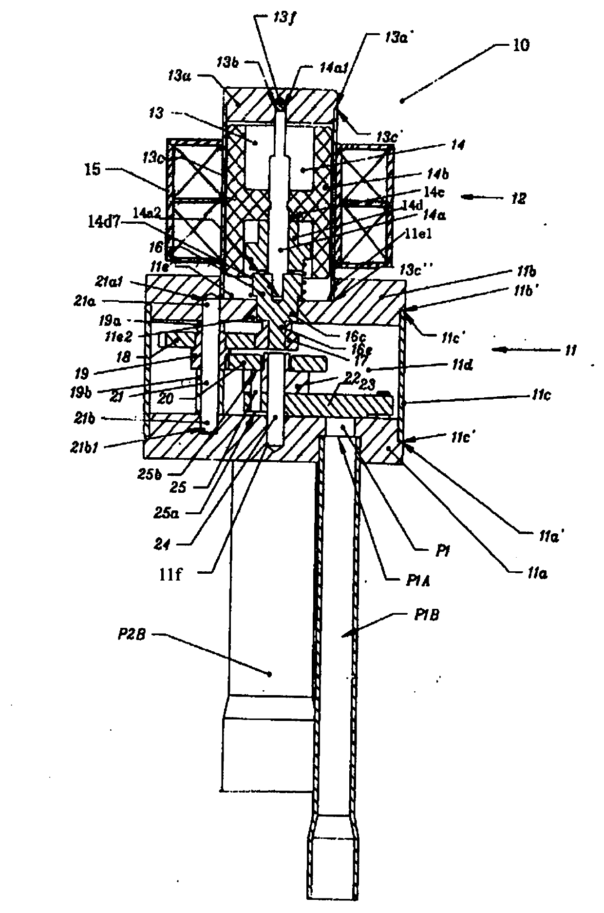
[0027] Such as figure 1 The illustrated electric three-way valve 10 is composed of a cylindrical housing 11 of a metal material such as stainless steel and a motor portion 12 . The above-mentioned motor part 12 is made of a non-magnetic metal material such as a cylindrical shell 13 made of stainless steel, a rotor 14 and a rotor shaft 14a disposed in the above-mentioned shell, and are externally embedded in the outside of the above-mentioned shell 13, and are fixed as a stator to drive the above-mentioned rotor 14. Composed of coils 15, the motor unit 12 is separated from the housing 11 and is arranged above the outer housing 11 in the figure.

[0028] The above-mentioned cylindrical housing 11 is made of a metal material such as a disc-shaped valve seat 11a of stainless steel, and a metal material such as a disc-shaped flat plate 11b of stainless steel disposed on the valve seat 11a as an upper end surface. A cylindrical side wall 11c is formed between the seat 11a and the p...


PUM


Abstract

The invention discloses a motor-driven three-way valve which comprises an input port, a plurality of output ports and a valve core. An opening of the input port is formed in the face of a valve seat, and the plurality of output ports are arranged at intervals and provided with a plurality of openings. The valve core rotates on the valve seat in a sliding mode under the driving force of a motor portion and opens and closes the plurality of output ports selectively. The motor portion serves as a separated individual and is installed on the outer side of the upper end face of a cylindrical outer cover for leading in a refrigerant. The valve seat is arranged on the opening portion at the lower end of the cylindrical outer cover. The valve core is driven by a gear device for transferring the driving force of the motor portion and arranged in the cylindrical outer cover. The cylindrical outer cover is formed by a lateral wall with a lateral opening portion and a top portion, the valve seat is arranged on the lateral opening portion, the other lateral opening portion is arranged on the top portion through the cylindrical wall portion, a casing fixed on the wall is arranged on the other lateral opening portion in an erection mode and installed on the cylindrical outer cover, and a motor is arranged in the casing. The valve avoids large-size coils, shortens occupied space, enables the shape of the valve core to be well balanced and ensures that the valve core can slide on the valve seat in the rotating direction.

Description

technical field [0001] The present invention relates to an electric three-way valve used in refrigeration cycles of air conditioners and refrigerators to switch flow paths. Background technique [0002] We know a valve that generally uses a stepping motor as a motor, and a gear is arranged at the lower end of the shaft of the rotor, and the driving force of the gear generated by the screwing of the gear and the gear driving the valve core makes the valve core rest on the valve seat. Upper sliding rotation, blockage opening on the one side of the flow path on the above-mentioned valve seat (referring to Japanese Patent Document 1, namely Japanese Patent Publication No. Hei 3-28583). In addition, we also know a valve, as mentioned above, through the driving force of the gear, the opening of the above-mentioned opening is controlled by the valve core slidingly driven on the above-mentioned valve seat (refer to Japanese Patent Document 2, that is, Japanese Patent Publication 20...

Claims


Application Information

Patent Timeline
Patent Type & Authority Applications(China)
IPC IPC(8): F16K11/06F16K31/04
Inventor 严卫林徐铭辉丁帅锋陈斌
Owner ZHEJIANG SANHUA INTELLIGENT CONTROLS CO LTD
Why Eureka
Try Eureka