Waste heat utilizing device for boiler furnace tail portion
A combustion chamber and waste heat technology, applied in preheating, feed water heaters, lighting and heating equipment, etc., can solve problems such as heat loss
Inactive Publication Date: 2013-10-30
XIANGYANG ZHONGLIJIE GRAIN OIL
View PDF0 Cites 0 Cited by
- Summary
- Abstract
- Description
- Claims
- Application Information
AI Technical Summary
Problems solved by technology
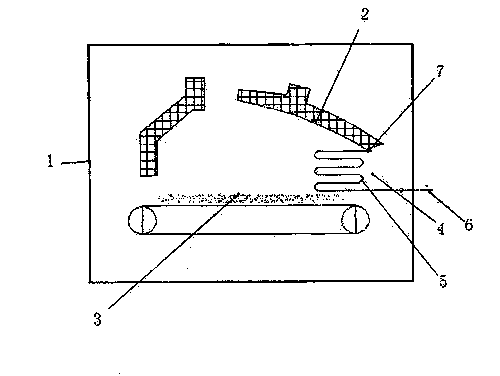
[0002] Boilers use grate circulation to burn coal. During the combustion process, the temperature in the combustion chamber can reach 650-900°C, and the residual temperature at the outlet of the flue gas discharged from the rear arch still reaches about 600°C. In order to facilitate full combustion The rear outlet is equipped with an induced draft fan, and a lot of waste heat is too late for the boiler to absorb, which will cause a huge loss of heat energy
Method used
View moreImage
Smart ImageViewing Examples
Examples
Embodiment Construction
[0009] As shown in the embodiment of the drawings: a waste heat utilization device is installed at the flue gas discharge port 4 at the tail of the combustion chamber 3 of the furnace body. The interface 7 communicates with the interior of the inner water bladder 2 . The waste heat utilization device is a circulating heat exchange tube 5 composed of "S" shaped multi-bending pipes.
Login to View More PUM
 Abstract
The invention provides a waste heat utilizing device for a boiler furnace tail portion. The waste heat utilizing device is arranged at the smoke discharging outlet position of the boiler furnace tail portion and provided with a water inlet connector capable of being connected with an external water supplying pipeline, and a water outlet connector at the other end is communicated with the inside of an inner water container. The waste heat utilizing device is an S-shaped circulation heat exchanging pipe formed by a multi-folding pipeline. During use, the water inlet connector is connected with the external water supplying pipe, in a boiler burning process, smoke discharged to the tail portion heats circulation supply water in the circulation heat exchanging pipe, and the supply water can serve as boiler water directly. Therefore, energy can be fully saved, and heat efficiency of a boiler is improved.
Description
technical field [0001] The invention relates to an energy-saving device configured and used in a boiler, in particular to a waste heat utilization device at the tail of a boiler combustion chamber. Background technique [0002] Boilers use grate circulation to burn coal. During the combustion process, the temperature in the combustion chamber can reach 650-900°C, and the residual temperature at the outlet of the flue gas discharged from the rear arch still reaches about 600°C. In order to facilitate full combustion The rear outlet is equipped with an induced draft fan, and a lot of waste heat is too late for the boiler to absorb, which will cause a huge loss of heat energy. Contents of the invention [0003] The purpose of the present invention is to provide a waste heat utilization device at the tail of the boiler combustion chamber, which can fully utilize the waste heat at the rear outlet and reduce the loss and waste of heat energy. [0004] The invention includes...
Claims
Login to View More Application Information
Patent Timeline
 IPC IPC(8): F22D1/02
Inventor 吴志杰刘进吕涢
Owner XIANGYANG ZHONGLIJIE GRAIN OIL
Features
- R&D
- Intellectual Property
- Life Sciences
- Materials
- Tech Scout
- Unparalleled Data Quality
- Higher Quality Content
- 60% Fewer Hallucinations
Learn More Browse by: Latest US Patents, China's latest patents, Technical Efficacy Thesaurus, Application Domain, Technology Topic, Popular Technical Reports.
© 2025 PatSnap. All rights reserved.Legal|Privacy policy|Modern Slavery Act Transparency Statement|Sitemap|About US| Contact US: help@patsnap.com

