
Color holographic image forming system

A holographic image and color technology, applied in the field of holographic film synthesis system, can solve the problems of poor holographic image visibility, insufficient image brightness, and inability to produce reconstructed images, so as to reduce the number of repeated exposures, improve brightness and color. effect of effect

Inactive Publication Date: 2013-10-30
E LON OPTRONICS
View PDF6 Cites 6 Cited by
  • Summary
  • Abstract
  • Description
  • Claims
  • Application Information

AI Technical Summary

Problems solved by technology

However, the negative is exposed repeatedly, which may lead to insufficient brightness of the reconstructed image, resulting in poor visibility of the holographic image, and the inability to produce a large-scale reconstructed image

Method used


Image

  • Color holographic image forming system
  • Color holographic image forming system
  • Color holographic image forming system

Examples


Embodiment Construction

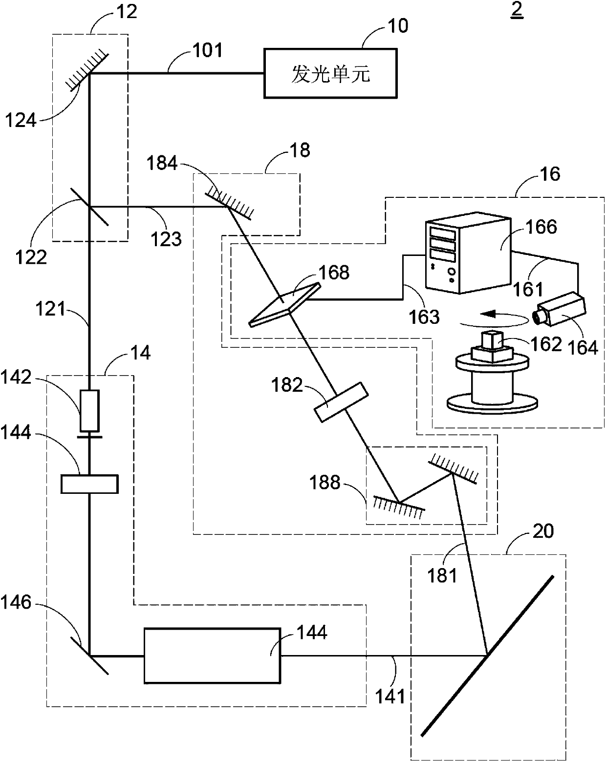
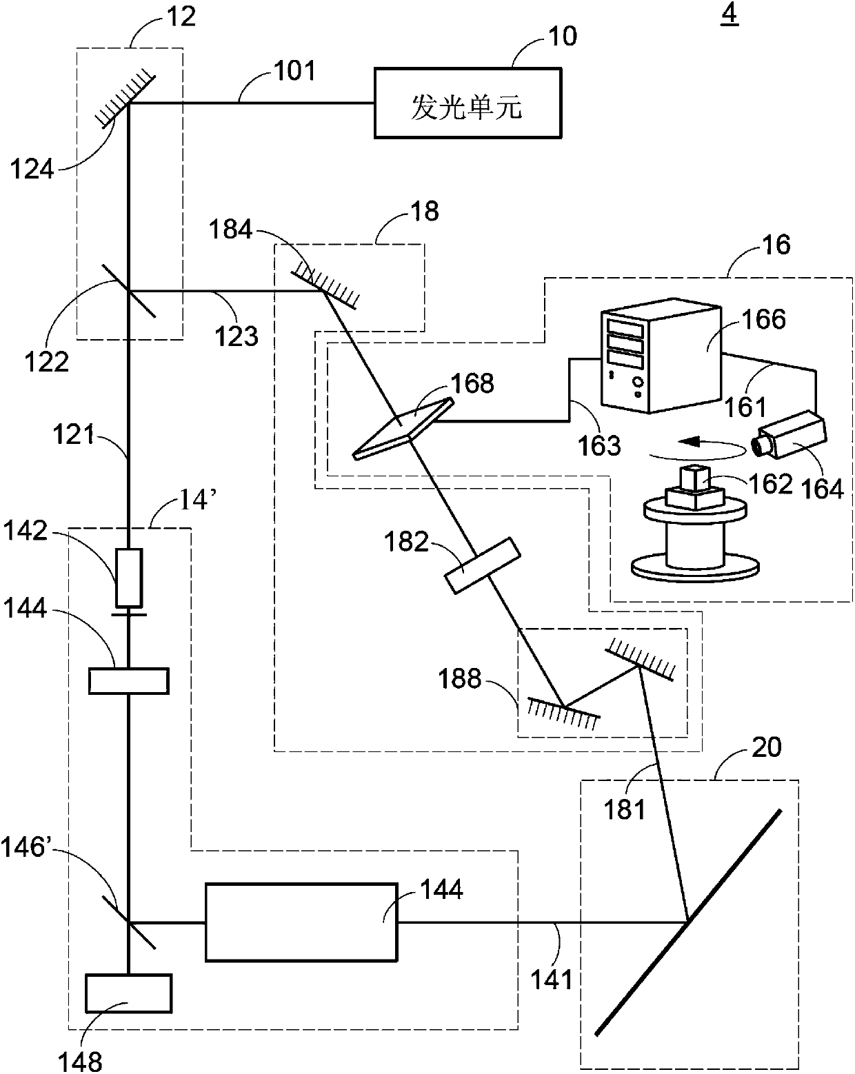
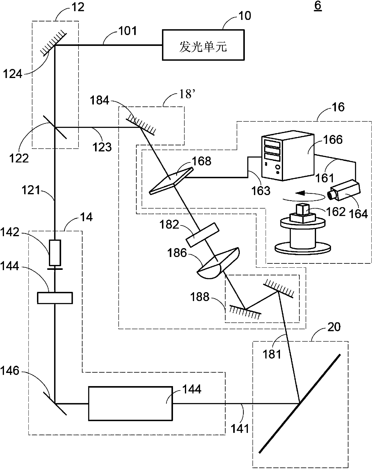
[0032] The holographic image synthesis system referred to below in the present invention can be applied to holographic synthesis systems of different imaging principles, such as rainbow holograms, reflective holograms, multi-view holograms, true color holograms or integral holograms, etc. Wait. Although a specific holographic composite system is shown in the drawings listed below, it is only used to illustrate the technology of the present invention, and is not intended to limit the scope of application of the present invention.

[0033] The reference light angle referred to below in the present invention refers to the included angle between the reference light and the film normal. When the film is a plane, the normal is single, but when the film is rolled into a cylindrical or conical shape, the normal has However, the present invention is not limited thereto, and the included angle between the reference light and the cut plane of the film can also be used as the definition. ...


PUM


Abstract

A color holographic image forming system is provided. The reference light wave is incident to the film at a fixed reference beam angle. By adjusting an included angle between the object light wave corresponding to respective monochromatic component images and the reference light wave, the reference light wave and the object light wave are interfered with each other to result in a plurality of interference fringes on the film. When a white light is projected on the film, the reconstructed image shows the color effect.

Description

technical field [0001] The invention relates to a synthesis system of holograms, in particular to a synthesis system of optical holograms. Background technique [0002] The existing optical holographic film uses a coherent light to irradiate the object, and the reflected light on the object surface or the direct penetrating light, that is, the object light, will shoot to the photosensitive plate, and then use another part of the coherent light as a reference light projection On the photosensitive plate, since the object light and the reference light come from the same beam of coherent light, interference will be formed on the photosensitive plate, forming many light and dark interference fringes, and the photosensitive plate will record these images to form a picture Holographic film, in which the shape of the interference pattern represents the phase relationship between the object light and the reference light, and the contrast between light and dark reflects the intensity...

Claims


Application Information

Patent Timeline
Patent Type & Authority Applications(China)
IPC IPC(8): G03H1/12
CPCG03H1/28G03H2001/2271G03H2001/0473G03H1/24G03H2210/42G03H2210/441G03H1/0465G03H2001/2685G03H1/12G03H1/268
Inventor 姚铭堂
Owner E LON OPTRONICS
Learn More