Railway vehicle antenna installation device and installation method thereof

A technology for installation devices and rail vehicles, which is applied in the direction of antenna supports/installation devices, etc., can solve the problems of inaccurate determination of antenna positioning size, complicated height adjustment process, unfavorable maintenance and maintenance, etc., shorten the manufacturing and installation cycle, and benefit Maintenance, light weight effect

Active Publication Date: 2013-10-30
CRRC QINGDAO SIFANG CO LTD
View PDF8 Cites 8 Cited by
  • Summary
  • Abstract
  • Description
  • Claims
  • Application Information

AI Technical Summary

Problems solved by technology

In this installation method, the antenna needs to be removed from the mounting base, and spacers are added or reduced between the mounting base and the antenna to adjust the height. At this time, the removal of the antenna is performed after getting off the car, which is extremely inconvenient and difficult to operate. Conducive to later maintenance and maintenance
During the assembly and manufacture of rolling stock, considering the dimensional deviation caused by the errors of various levels and the deflection of the car body, the positioning size of the antenna cannot be accurately determined, and the randomness is relatively large. During installation, the antenna can only be pre-installed and the height adjustment process Very complicated, time-consuming, and labor-intensive for workers

Method used


Image

  • Railway vehicle antenna installation device and installation method thereof
  • Railway vehicle antenna installation device and installation method thereof
  • Railway vehicle antenna installation device and installation method thereof

Examples


Embodiment Construction

[0032] Below in conjunction with accompanying drawing and specific embodiment the present invention is described in further detail:

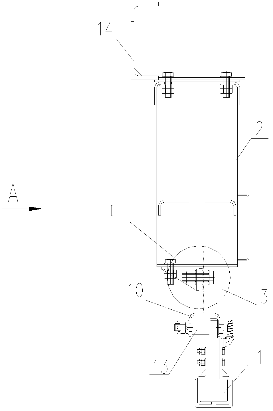
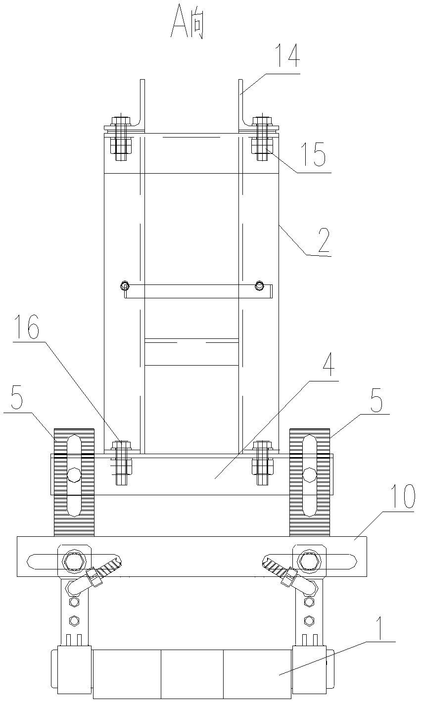
[0033] Such as figure 1 with figure 2 As shown, a rail vehicle antenna installation device includes an antenna 1, and the antenna 1 is installed under the vehicle. In order to receive signals stably, the height of the lower surface of the antenna 1 from the rail surface should be strictly controlled within a specified range. This embodiment Among them, the height of the lower surface of the antenna 1 from the rail surface is 155±5mm.

[0034] Such as figure 1 with figure 2 As shown, the device also includes a mounting base 2. The mounting base 2 is a metal frame structure. The mounting base 2 is fixedly installed on the beam 14 at the bottom of the vehicle body through the bolt 15 on the top. The height between the antenna 1 and the mounting base 2 is adjusted. Body 3 connection.

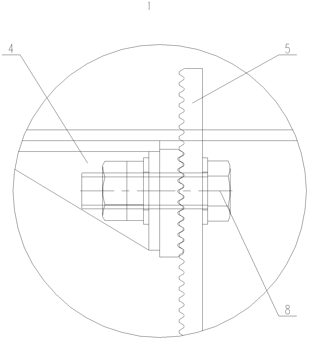
[0035] Such as figure 2 As shown, the height adjustment...


PUM


Abstract

The invention relates to a railway vehicle antenna installation device and an installation method of the railway vehicle antenna installation device. The railway vehicle antenna installation device comprises an antenna, and further comprises an installing base which is fixedly connected with a vehicle body. The antenna and the installing base are connected through a height adjustment mechanism. The height adjustment mechanism comprises a transition base and an adjustment base, wherein the transition base and the adjustment base are connected with each other, the transition base is fixedly connected with the installing base, the antenna is fixedly connected to the adjustment base, and the adjustment base moves up and down relative to the transition base in the height direction so as to realize the height adjustment of the antenna. The railway vehicle antenna installation device is simple in overall structure, light in weight and low in manufacturing cost; the height adjustment of the antenna is simple and fast; the complex process that the number of gaskets is increased or reduced to adjust the height of the antenna in the past is ended, and the height adjustment process of the antenna off the vehicle body is simplified; integrated installation is realized, and secondary dismounting and mounting in later adjustment are avoided; the manufacturing and installation period is shortened, labor intensity is lowered for workers, and later maintenance is facilitated.

Description

technical field [0001] The invention relates to an antenna installation device, in particular to an antenna installation device used on a rail vehicle and an installation method thereof, and belongs to the technical field of rail vehicle design. Background technique [0002] At present, the antenna equipment under the rail vehicle is scattered in the locomotive equipment compartment. Since the receiving signal needs to be within a relatively stable height area with the rail, the antenna needs to be accurately measured before the vehicle is manufactured. The height value of the track , the height deviation requirement is 5mm, as long as it exceeds the range of the standard value +5mm, it will be determined that the antenna installation does not meet the height requirements, and the antenna height needs to be readjusted. [0003] In the Chinese patent "an antenna installation device" with the patent number of 201120008188.6, an antenna installation device for rail vehicles is ...

Claims


Application Information

Patent Timeline
IPC IPC(8): H01Q1/12
Inventor 刘志坤李春国万国强李宏孙彦
Owner CRRC QINGDAO SIFANG CO LTD
Why Eureka
Try Eureka