
Automatic bonding machine for connection between chip and glass circuit

A glass circuit and bonding machine technology, which is applied in the direction of assembling printed circuits with electric components, can solve the problems of high labor cost, more manpower, and low efficiency, and achieve the effect of high attachment accuracy, less manpower, and high efficiency

Active Publication Date: 2013-10-30
SHENZHEN LIANDE AUTOMATION EQUIP
View PDF4 Cites 1 Cited by
  • Summary
  • Abstract
  • Description
  • Claims
  • Application Information

AI Technical Summary

Problems solved by technology

For the current semi-automatic equipment, the efficiency is low, the yield rate is poor, and the manpower is too much.
For the current fully automatic COG equipment, the bonding capacity of a small-sized single IC is 4 seconds / piece, the ACF attachment accuracy is ±0.2mm, and the post-press bonding accuracy is ±5um. At the same time, as the product requirements become more and more High, labor costs are getting higher and higher, so higher requirements are put forward for this type of equipment, the production capacity is 3.5 seconds / piece, the ACF attachment accuracy is ±0.1mm, and the bonding accuracy after pressing is ±3um, so that the current Some equipment in the market cannot meet the market demand

Method used


Image

  • Automatic bonding machine for connection between chip and glass circuit
  • Automatic bonding machine for connection between chip and glass circuit
  • Automatic bonding machine for connection between chip and glass circuit

Examples


Embodiment Construction

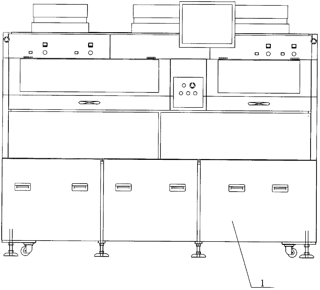
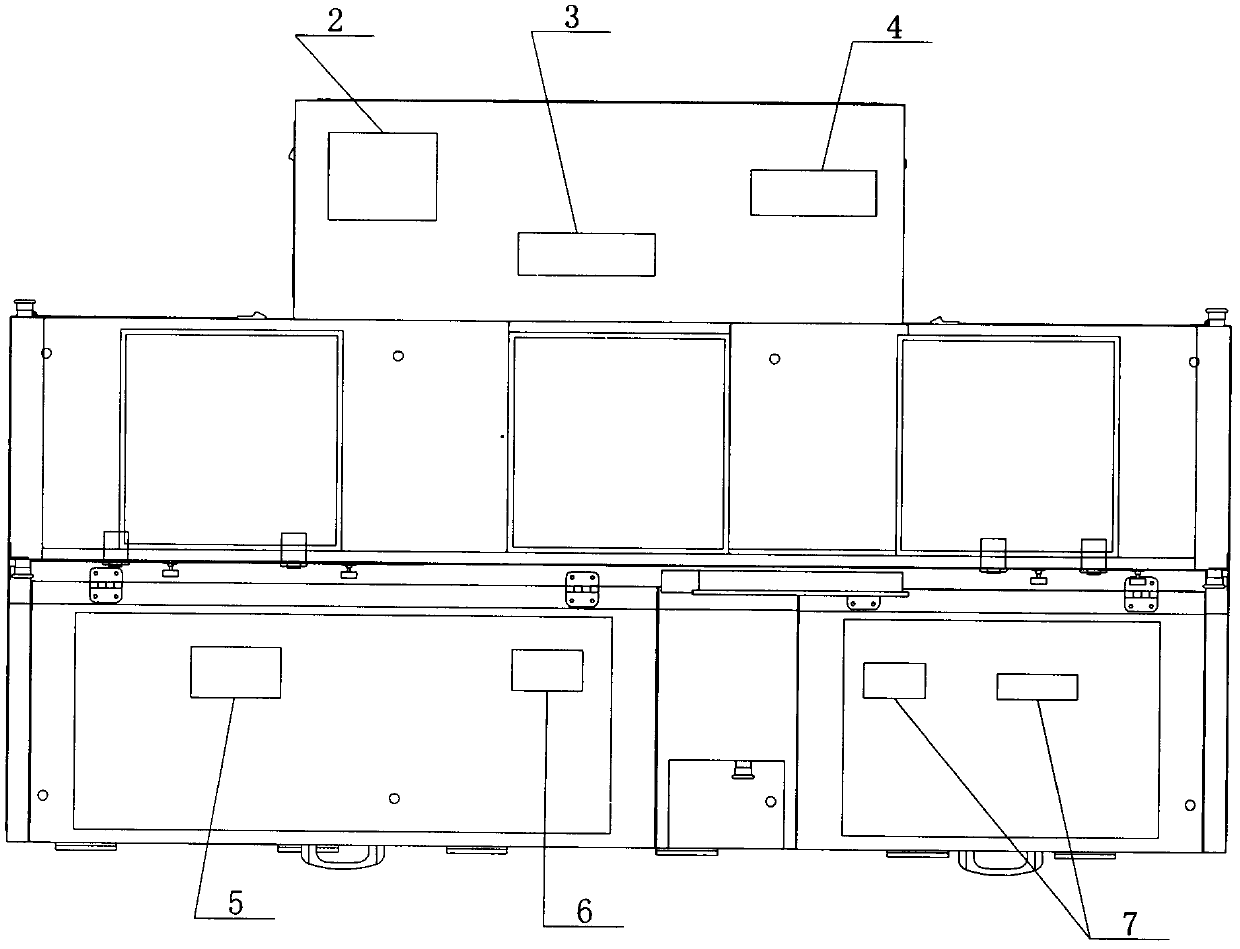
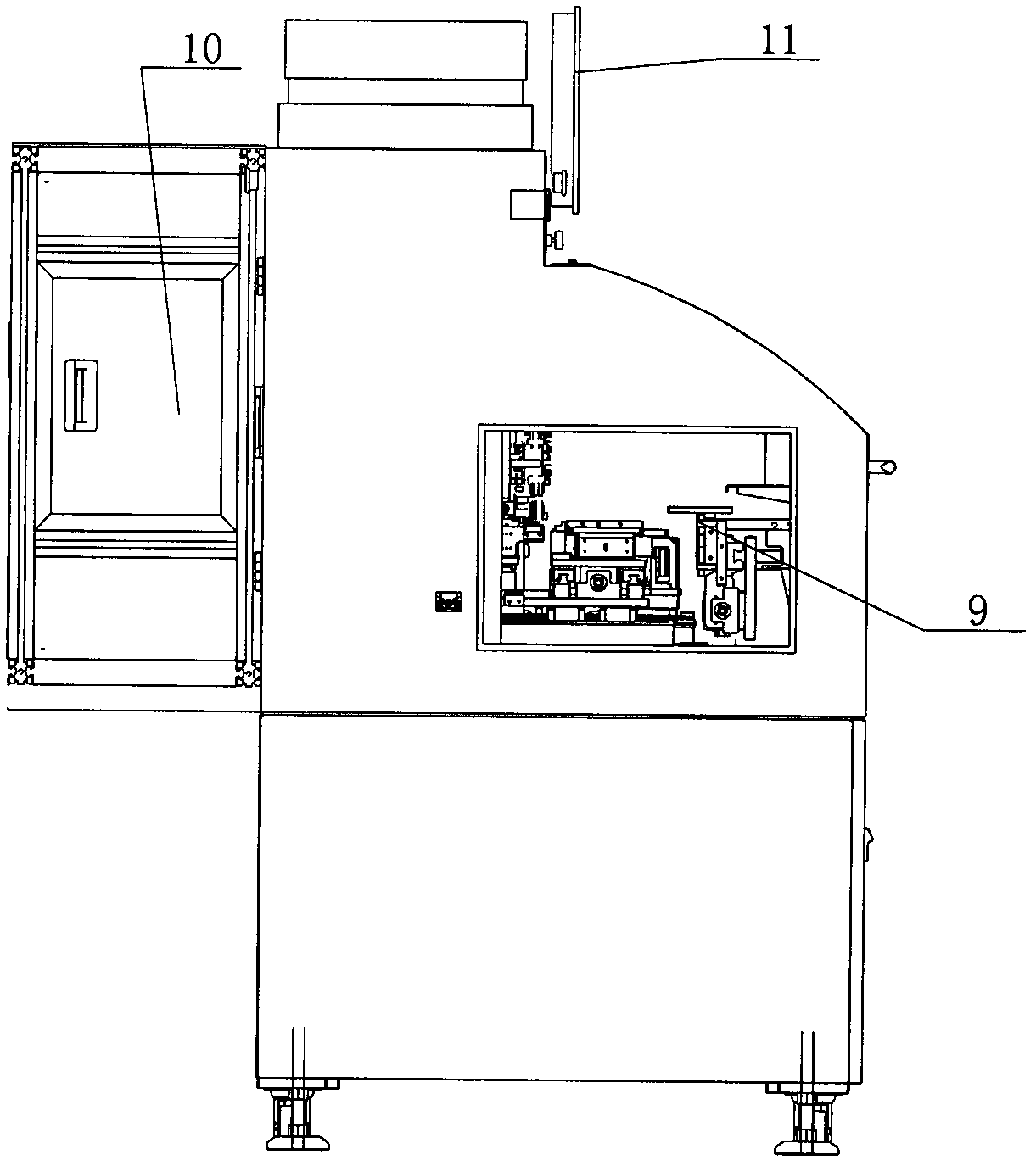
[0017] see Figure 1-3 , the specific embodiment adopts the following technical solutions: it includes an automatic bonding machine body 1, an IC feeding part 2, an IC disc work area 3, an IC empty disc recovery area 4, an ACF part 5, a pre-press part 6, and the press part 7. Manipulator part 9, IC handling mechanism 10 and display 11, IC feeding part 2 is set at the rear of automatic bonding machine body 1, IC disk working area 3 is set on the right side of IC feeding part 2, and IC empty disk is recovered Zone 4 is set on the right side of the IC disk working area 3, the ACF part 5 is set on the left side of the front part of the automatic bonding machine body 1, the pre-pressing part 6 is set on the right side of the ACF part 5, and the pre-pressing part 7 is set on the pre-pressing part 5. On the right side of the pressing part 6, the manipulator 9 is arranged on the left side of the automatic bonding machine body 1, the IC transport mechanism 10 is arranged at the rear of...


PUM


Abstract

The invention provides an automatic bonding machine for connection between a chip and a glass circuit, and relates to the technical field of automatic bonding machines. An IC feeding portion (2) is arranged on the rear portion of an automatic bonding machine body (1), an IC disc working area (3) is arranged on the right side of the IC feeding portion (2), an IC empty disc recovery area (4) is arranged on the right side of the IC disc working area (3), an ACF portion (5) is arranged on the left side of the front portion of the automatic bonding machine body (1), a pre-pressing portion (6) is arranged on the right side of the ACF portion (5), a currently pressing portion (7) is arranged on the right side of the pre-pressing portion (6), a mechanical arm portion (9) is arranged on the left side face of the automatic bonding machine body (1), and an IC carrying mechanism (10) is arranged on the rear portion of the automatic bonding machine (1). The automatic bonding machine for connection between the chip and the glass circuit is high in efficiency, little in required manpower and high in ACF attaching accuracy due to the fact that a detection mechanism is arranged.

Description

Technical field: [0001] The invention relates to the technical field of automatic bonding machines, in particular to an automatic bonding machine for connecting chips and glass lines. Background technique: [0002] At present, the automatic bonding machine (hereinafter collectively referred to as COG) for connecting chips and glass lines is composed of semi-automatic equipment, ACF attachment equipment, Chip (IC) pre-pressing equipment, Chip (IC) local pressing equipment and other stand-alone machines. Fractional automatic COG consists of a glass loading unit, an ACF attachment unit, a Chip (IC) loading unit, a Chip (IC) pre-pressing unit, a Chip (IC) local pressing unit, and a product unloading unit. For the current semi-automatic equipment, there are disadvantages such as low efficiency, poor yield rate, and many manpower. For the current fully automatic COG equipment, the bonding capacity of a small-sized single IC is 4 seconds / piece, the ACF attachment accuracy is ±0.2m...

Claims


Application Information

Patent Timeline
Patent Type & Authority Applications(China)
IPC IPC(8): H05K3/30
Inventor 聂泉龙桂华谢家达
Owner SHENZHEN LIANDE AUTOMATION EQUIP
Learn More