Patch device and automatic patch method

A patch device and patch technology, applied in the direction of material gluing, connecting components, mechanical equipment, etc., can solve the problems of labor resource consumption and low production efficiency, and achieve the effects of convenient work, increased success rate, and high replacement efficiency

Pending Publication Date: 2022-03-01
SHANGHAI VEI SHENG AUTO PARTS MFG CO LTD
View PDF6 Cites 0 Cited by
  • Summary
  • Abstract
  • Description
  • Claims
  • Application Information

AI Technical Summary

Problems solved by technology

Pasting by hand is labor-intensive and the production efficiency is low

Method used


Image

  • Patch device and automatic patch method
  • Patch device and automatic patch method
  • Patch device and automatic patch method

Examples


Embodiment 1

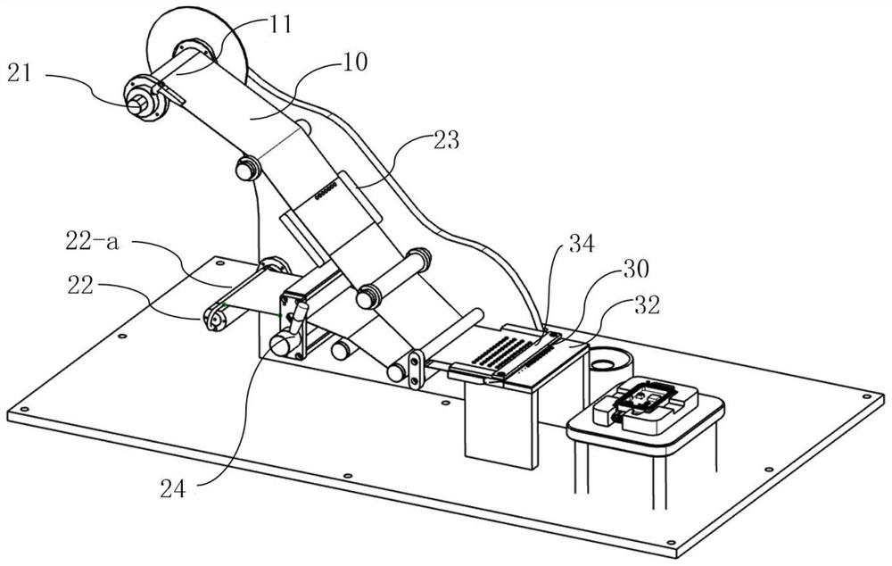
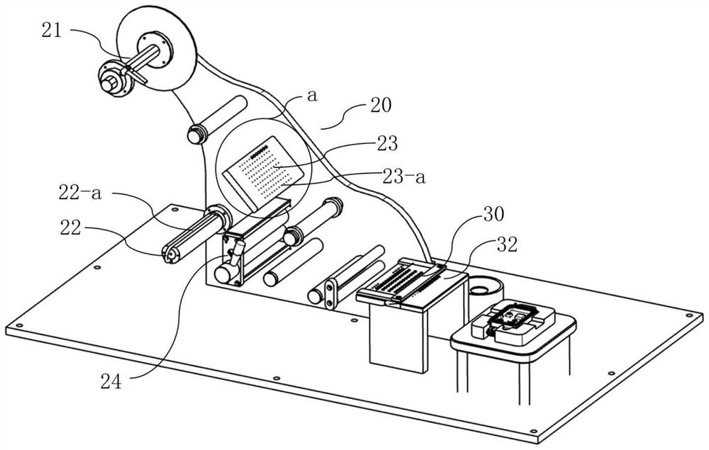
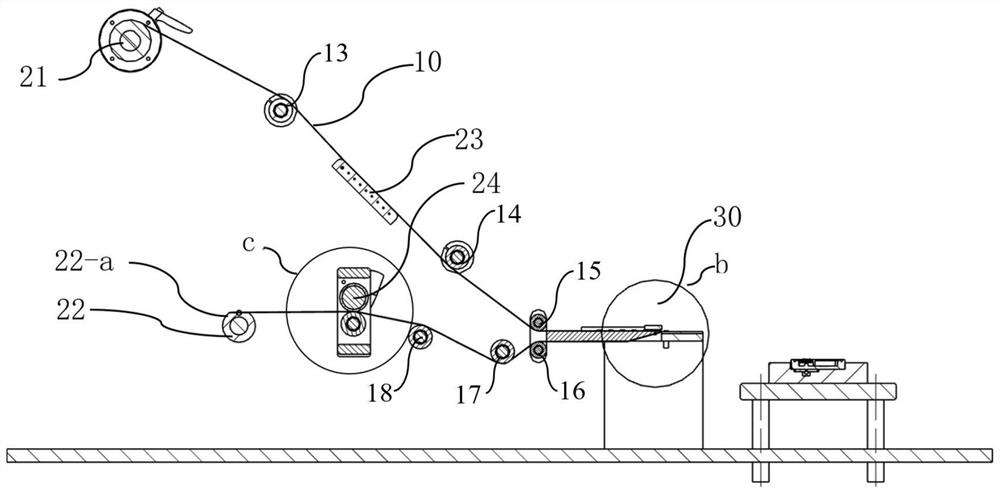
[0067] This embodiment is a patch device, such as Figure 7 As shown, this placement device comprises: feeding mechanism 20, unloading mechanism 30 and material taking mechanism 40. The device can paste the patch 12 to the object to be pasted. The patch 12 is a soft and thin piece with stickiness on one side, such as the air-permeable sticker used on the car radar casing, or the film on the back cover of the mobile phone and other parts. Such as figure 1 As shown, the patch 12 is pasted on the surface of the material tape 10 before the patch 12 and the object to be pasted are processed into a finished product, and the material tape 10 pasted with the patch 12 is wound on the surface of the reel 11, which is convenient for transportation and sale .

[0068] What is different from ordinary conveyor belts is that the patch 12 itself is sticky and cannot fall out of the material belt by gravity. But patch 12 has certain intensity and length again, so the present invention has u...

Embodiment 2

[0075] This embodiment is a patch device. This embodiment includes the feeding mechanism 20, the unloading mechanism 30 and the retrieving mechanism 40 in the first embodiment, and optimizes different mechanisms to achieve different technical effects. The same parts I won't repeat them here.

[0076] Specifically, the working surface 38 of the anti-adhesive plate 32 is lower than the first sliding surface 31-a, and the success rate of peeling off the patch 12 is improved by forming a drop between the anti-adhesive plate 32 and the first sliding surface 31-a. The surface of the first sliding surface 31-a is equipped with a pressing plate 34, and there is a second gap 35 between the pressing plate 34 and the surface of the first sliding surface 31-a, and the second gap 35 is greater than the sum of the thickness of the strip 10 and the thickness of the patch 12 , and leave a certain safety distance. Insufficient bonding of the patch 12 and the tape 10 is prevented, causing the ...

Embodiment 3

[0086] This embodiment is a patch device. This embodiment includes the feeding mechanism 20, the unloading mechanism 30 and the retrieving mechanism 40 in Embodiment 1 and Embodiment 2, as well as their specific structures. On this basis, this embodiment adds The detection mechanism 50 is provided, and the same parts will not be repeated here.

[0087] Specifically, the detection mechanism 50 includes a first probe 51 and a second probe 52. The first probe 51 is installed on one side of the adsorption column 41, and the sensing direction is toward the surface where the working surface 38 is located, and is used to detect the surface of the patch 12 on the working surface 38. The arrangement on the surface; the second probe 52 is lower than the plane where the working surface 38 is located, and the sensing direction faces the plane where the working surface 38 is located, and is used to detect the arrangement of the patch 12 on different adsorption columns 41 .

[0088] In prac...


PUM


Abstract

The invention discloses a chip mounting device and an automatic chip mounting method, and the chip mounting device comprises a feeding mechanism which comprises a material taking shaft and a material receiving shaft, and the axial directions of the material taking shaft, the material receiving shaft and a reel are consistent; the discharging mechanism comprises a discharging plate and an anti-sticking plate, the surface of the discharging plate is provided with a first sliding face and a second sliding face of the material belt, the included angle between the first sliding face and the second sliding face is an acute angle, and a material belt corner is formed through arc transition; the working surface of the anti-sticking plate is lapped at the corner, and the first gap is larger than the thickness of the material belt and smaller than the length of the patch in the conveying direction; and the material taking mechanism comprises an adsorption column for stripping the patch from the working surface, and a moving assembly for moving the adsorption column to the surface of the to-be-pasted piece for pasting. Through the specific structure of the feeding mechanism, the discharging mechanism and the material taking mechanism, the purpose that the device can conveniently strip the patch from the material belt is achieved.

Description

technical field [0001] The invention relates to the technical field of chip placement devices, in particular to a chip placement device and an automatic chip placement method. Background technique [0002] With the rapid development of the electronics industry and the automobile industry, the requirements for product production efficiency are getting higher and higher. Especially in the production process of vehicle-mounted radar, because the casing of vehicle-mounted radar needs to be pasted with air-permeable stickers, one side of the air-permeable sticker is sticky, and the sticky side is pasted on a smooth material tape before use, and it is convenient to roll it together by reel shipping and trading. The traditional process is to manually peel off the air-permeable sticker from the material tape, and then paste it into the housing of the vehicle radar. Using manual pasting not only consumes labor resources, but also has low production efficiency. [0003] Therefore, ...

Claims


Application Information

Patent Timeline
Patent Type & Authority Applications(China)
IPC IPC(8): F16B11/00
CPCF16B11/006
Inventor 齐照山林东峰何育林陈明齐文家
Owner SHANGHAI VEI SHENG AUTO PARTS MFG CO LTD
Why Eureka
Try Eureka