
Clutch master cylinder

A clutch master pump and pump body technology, applied in clutches, fluid-driven clutches, non-mechanical-driven clutches, etc., can solve the problems of slow hydraulic oil backfilling the liquid supply cavity, and the pressure of the liquid outlet is not easy to build, etc., and achieves easy buildup speed. , enhance elasticity, the effect of rapid rise

Inactive Publication Date: 2013-11-06
宁波神丰汽车部件有限公司
View PDF7 Cites 2 Cited by
  • Summary
  • Abstract
  • Description
  • Claims
  • Application Information

AI Technical Summary

Problems solved by technology

[0003] The purpose of the present invention is to overcome the shortcomings of the current clutch master cylinder that the pressure of the liquid outlet hole is not easy to build up and the speed of hydraulic oil backfilling the liquid supply chamber is relatively slow, and provide a method that is easy to build up the pressure of the liquid outlet hole and the backfill pressure of the hydraulic oil. Faster clutch master cylinder

Method used


Image

  • Clutch master cylinder
  • Clutch master cylinder

Examples


Embodiment Construction

[0017] The present invention will be further described below in conjunction with the accompanying drawings.

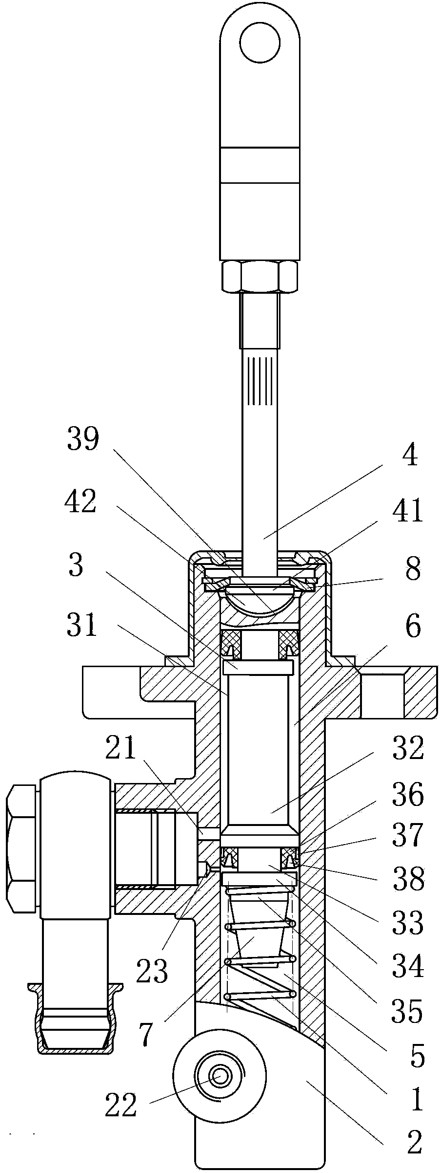
[0018] as attached figure 1 , attached figure 2 Shown: a clutch master cylinder, including a pump body 2, a piston 3, a return spring 1 for resetting the piston 3, and a push rod 4 whose front end extends into the pump body 2 to push the piston 3; the front end of the piston 3 is connected to the pump The pressure chamber 5 is formed between the body 2; the side wall of the piston 3 is provided with an annular groove 31; the liquid supply chamber 6 is formed between the annular groove 31 and the side wall of the pump body 2; the pump body 2 has a The liquid inlet hole 21 communicated with the chamber 6 and the liquid outlet hole 22 communicated with the pressure chamber 5; the pump body 2 has a liquid hole 23 with one end communicated with the liquid inlet hole 21; The other end of the liquid hole 23 communicates with the pressure chamber 5 .

[0019] The piston 3 ...


PUM


Abstract

The invention relates to the field of automobile clutches and aims to provides a clutch master cylinder which comprises a pump body, a piston, a reset spring and a push rod, wherein the reset spring is used for resetting the piston; the front end of the push rod stretches into the pump body, so as to push the piston; a pressure cavity is formed by the front end of the piston and the pump body; an annular groove is formed in a side wall of the piston; a liquid feeding cavity is formed between the annular groove and a side wall of the pump body; a liquid inlet hole communicated with the liquid feeding cavity and a liquid outlet hole communicated with the pressure cavity are formed in the pump body; a liquid passing through hole communicated with the liquid inlet hole is formed in one end of the pump body; if a clutch pedal is not trampled, the piston is in an initial position; the other end of the liquid passing through hole is communicated with the pressure cavity. When the clutch master cylinder works, the pressure of the liquid outlet hole is easy to establish, and the pressure cavity is backfilled with hydraulic oil faster.

Description

technical field [0001] The invention relates to the field of automobile clutches, in particular to a clutch master cylinder. Background technique [0002] The clutch master cylinder is a part connected to the clutch pedal and connected to the clutch booster through the oil pipe. Its function is to collect pedal stroke information and realize the separation of the clutch through the action of the booster. The invention of Chinese Patent Publication No. CN102367844A discloses an automobile clutch master cylinder assembly, including a cylinder body, a piston is slidably installed in the cylinder body, a spring seat is fixed at the rear end of the piston, and a cushion is placed between the spring seat and the cylinder body. Spring, the front end of the piston is connected with a push rod, the end of the spring seat is covered with a dust cover, the front end of the push rod is screwed with a nut, the side wall of the cylinder body is inserted with an oil inlet joint, and an oil...

Claims


Application Information

Patent Timeline
Patent Type & Authority Applications(China)
IPC IPC(8): F16D25/12F16D48/02
Inventor 徐文翁国畅
Owner 宁波神丰汽车部件有限公司
Learn More