
check valve

A technology for check valves and valve seats, applied in valve details, control valves, valve devices, etc., can solve the problems of not having a spring closing valve force mechanism, shortening the life of check valves, increasing the number of parts, etc., to achieve guaranteed life , the effect of suppressing abnormal noise and increasing the number of parts

Active Publication Date: 2016-03-09
SAGINOMIYA SEISAKUSHO INC
View PDF7 Cites 4 Cited by
  • Summary
  • Abstract
  • Description
  • Claims
  • Application Information

AI Technical Summary

Problems solved by technology

[0006] However, when the check valve is installed after the compressor, or when the piping is bent, there is a swirling component in the fluid flowing through the check valve, and the check valve placed vertically is moved by its own weight. The valve is closed, so it does not have a valve closing force mechanism such as a spring
[0007] Therefore, in the case of a check valve that closes the valve by its own weight, when the valve is opened, the valve body may rotate inside the valve body (valve chamber), which may cause abnormal noise, deformation, wear, and shorten the check valve. valve life
On the other hand, if the check valve is equipped with a spring as the valve closing urging mechanism, the rotation of the valve body can be prevented, but in this case, a fluid pressure exceeding the force of the spring is required to open the valve, and the number of parts will also increase. , so it is not preferred

Method used


Image

  • check valve
  • check valve
  • check valve

Examples


Embodiment Construction

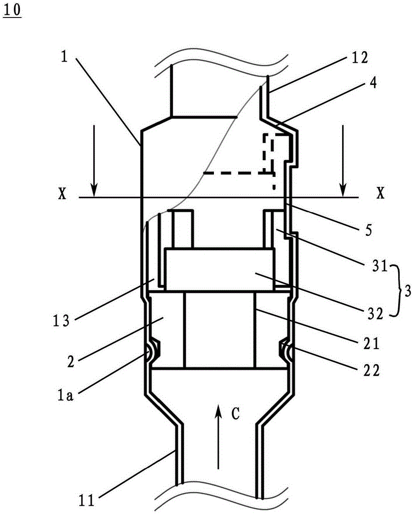
[0036] Hereinafter, the check valve of the present invention will be described with reference to the drawings.

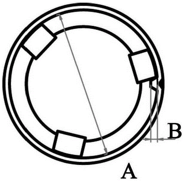
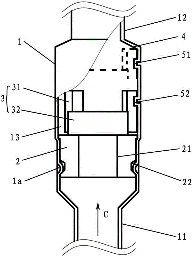
[0037] The check valve 10 is a vertically placed check valve, and includes a metal valve body 1 and a valve body 3 . A valve seat member 2 serving as a “valve seat portion” is provided inside the valve main body 1 . In the valve body 1 , a small-diameter inlet pipe portion 11 and an outlet pipe portion 12 are integrally formed (for example, press-processed), and a large-diameter valve chamber 13 is formed in the center thereof. In addition, a limiting portion 4 is formed on a boundary portion between the outlet pipe portion 12 and the valve chamber 13 of the valve main body 1 . A valve port 21 is formed at the center of the valve seat member 2 attached to the valve main body 1 by being press-fitted toward the introduction pipe portion 11 in the valve chamber 13 . Furthermore, caulking and fixing are performed by a concave portion 22 formed on the outer periphery o...


PUM


Abstract

The invention provides a check valve which comprises a valve seat component, a valve main body of a limiting part, a circular plate part, a plurality of guide parts protruding from the periphery of the circular plate part and a valve body capable of moving between the valve seat component and the limiting part and losing the valve due to dead weight, wherein fluid passages are formed in the periphery of the circular plate part by gaps between the adjacent guide parts; on the moving range part of the valve main body corresponding to the valve body, convex parts protruding from the inner side of the valve main body are arranged; the condition that the valve body rotates due to the rotation component of the fluid cannot happen in the check valve.

Description

technical field [0001] The present invention relates to a check valve which is in an open state by the pressure of fluid flowing forward and in a closed state by the pressure of fluid flowing in the reverse direction. Background technique [0002] Conventionally, in a vapor compression refrigeration cycle, a check valve is often used as an element constituting a circulation loop. The purpose of the check valve is to open the valve and form a flow channel through the forward flow of the fluid, and to close the valve and close the flow channel through the reverse flow. [0003] In addition, as this kind of check valve, there are generally check valves in which the valve body is biased by a spring in order to ensure a reliable closed state and a degree of freedom in the installation posture, and in order to reduce the valve opening pressure loss when the valve is opened. This is a "micro differential pressure operated" check valve that closes the valve by its own weight withou...

Claims


Application Information

Patent Timeline
Patent Type & Authority Patents(China)
IPC IPC(8): F16K15/00F16K47/02
Inventor 渡边秀刚横田健久
Owner SAGINOMIYA SEISAKUSHO INC
Learn More