Power distribution cabinet framework

A technology for power distribution cabinets and frames, applied in the field of power distribution cabinet frames, can solve the problems of increased damage to busbar clamps 10, lower product quality, and increased costs, and achieve the effects of high stability, good strength, and precise positioning

Active Publication Date: 2013-11-06
ANHUI MINGYUAN POWER EQUIP MFR
View PDF8 Cites 3 Cited by
  • Summary
  • Abstract
  • Description
  • Claims
  • Application Information

AI Technical Summary

Problems solved by technology

The top plate of the cabinet body firmly seals the busbar in the cabinet. When installing the busbar, it must be interspersed from the first cabinet. Large quantity, high cost of manpower and material resources
In addition, due to the interspersed force, the number of damaged busbar clamps 10 is also increasing, and while the cost increases, the product quality is reduced.

Method used


Image

  • Power distribution cabinet framework
  • Power distribution cabinet framework
  • Power distribution cabinet framework

Examples


Embodiment Construction

[0038] The specific implementation manner of the present invention will be described in further detail below by describing the best embodiment with reference to the accompanying drawings.

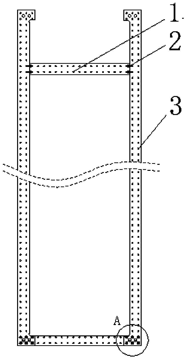
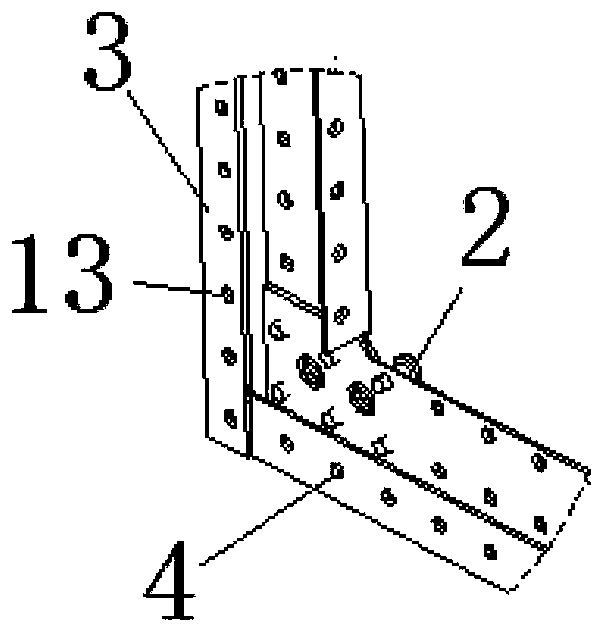
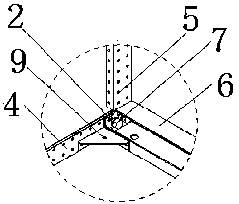
[0039] figure 1 and figure 2 It is a structural schematic diagram of the side panel of the distribution cabinet frame of the present invention; image 3 It is a schematic diagram of the installation of the side piece and the connecting beam of the distribution cabinet frame of the present invention; Figure 4 It is a schematic diagram of the installation of the flip-top cover plate and the cabinet body of the power distribution cabinet frame of the present invention; Figure 5 It is a structural schematic diagram of the frame of the distribution cabinet of the present invention; Figure 6 It is a schematic structural diagram of a power distribution cabinet assembled from a frame of the power distribution cabinet according to the present invention.

[0040] Such as figure 1 and fig...


PUM


Abstract

The invention discloses a power distribution cabinet framework which comprises lateral plates and a connecting beam between the lateral plates. Each lateral plate is formed by connecting a busbar clamp mounting beam, a stand column and a cross beam, wherein the cross beam and the stand column are connected in an inserted mode and then connected through self-tapping screws to form the lateral plate; the two ends of the connecting beam are provided with mountings holes respectively, and the end portions of the self-tapping screws extend out of the lateral plate and then extend into the mountings holes; the connecting beam is connected with the lateral plate through bolts; a structural strengthening support is arranged between the cross beam and the connecting beam; the two ends of the busbar clamp mounting beam are connected with the stand column respectively through the self-tapping screws. According to the power distribution cabinet framework, the cross beams and the stand columns are connected in the inserted mode and then tightly pressed and connected through the self-tapping screws, and therefore accurate positioning of the lateral plates is realized; after the end portions of the self-tapping screws are inserted in the mounting holes of the connecting beam, the lateral plates and the connecting beam are connected in a fastening mode through the high-strength bolts, and therefore the connection strength and stability of the lateral plates and the connecting beam are good; due to the connection structure between the stand columns, the cross beams and the connecting beam, the power distribution cabinet framework is high in installation accuracy, easy to install and operate, and capable of guaranteeing the quality of a power distribution cabinet product.

Description

technical field [0001] The invention relates to a high and low voltage power distribution cabinet, in particular to a frame of a power distribution cabinet. Background technique [0002] At present, KB profiles and 8MF welded frame side pieces are commonly used frames in the field of power distribution cabinets, but these two frames have many disadvantages, such as Figure 7 to Figure 9 As shown in the KB profile assembly diagram, the G-type connecting beam 6 is welded with a plug 21 with a boss 20 , and the welding level directly affects the cooperation between the G-type connecting beam 6 and the column 3 . [0003] When the boss 20 on the connecting beam 6 penetrates the modulus hole on the column 3, the boss 20 and the column 3 are clearance fit, the column 3 swings from side to side, and the angle between the column 3 and the beam 4 cannot be 9° degree; even if the bolt group 18 and the threaded pressure plate 19 are pressed tighter, the frame is still unstable under th...

Claims


Application Information

Patent Timeline
Patent Type & Authority Applications(China)
IPC IPC(8): H02B1/01
Inventor 周建祥
Owner ANHUI MINGYUAN POWER EQUIP MFR
Why Eureka
Try Eureka