Overcurrent detection and protection circuit

A protection circuit and over-current detection technology, which is applied in the direction of protection against over-current, can solve problems such as MOSFET damage of driving devices, and achieve the effect of circuit protection

Active Publication Date: 2013-11-13
BEIJING JINGWEI HIRAIN TECH CO INC
View PDF9 Cites 15 Cited by
  • Summary
  • Abstract
  • Description
  • Claims
  • Application Information

AI Technical Summary

Problems solved by technology

[0005] In view of this, the present invention provides an overcurrent detection and protection circuit to solve the problem in the prior art that it takes a period of time from MCU receiving an overcurrent signal to performing a shutdown operation. During this period, due to excessive current , may have caused the problem of MOSFET damage of the driving device. The technical solution is as follows:

Method used


Image

  • Overcurrent detection and protection circuit
  • Overcurrent detection and protection circuit

Examples


Embodiment Construction

[0029] The following will clearly and completely describe the technical solutions in the embodiments of the present invention with reference to the accompanying drawings in the embodiments of the present invention. Obviously, the described embodiments are only some, not all, embodiments of the present invention. Based on the embodiments of the present invention, all other embodiments obtained by persons of ordinary skill in the art without making creative efforts belong to the protection scope of the present invention.

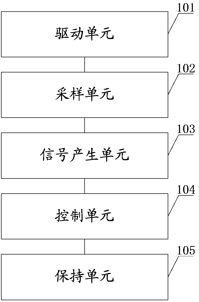
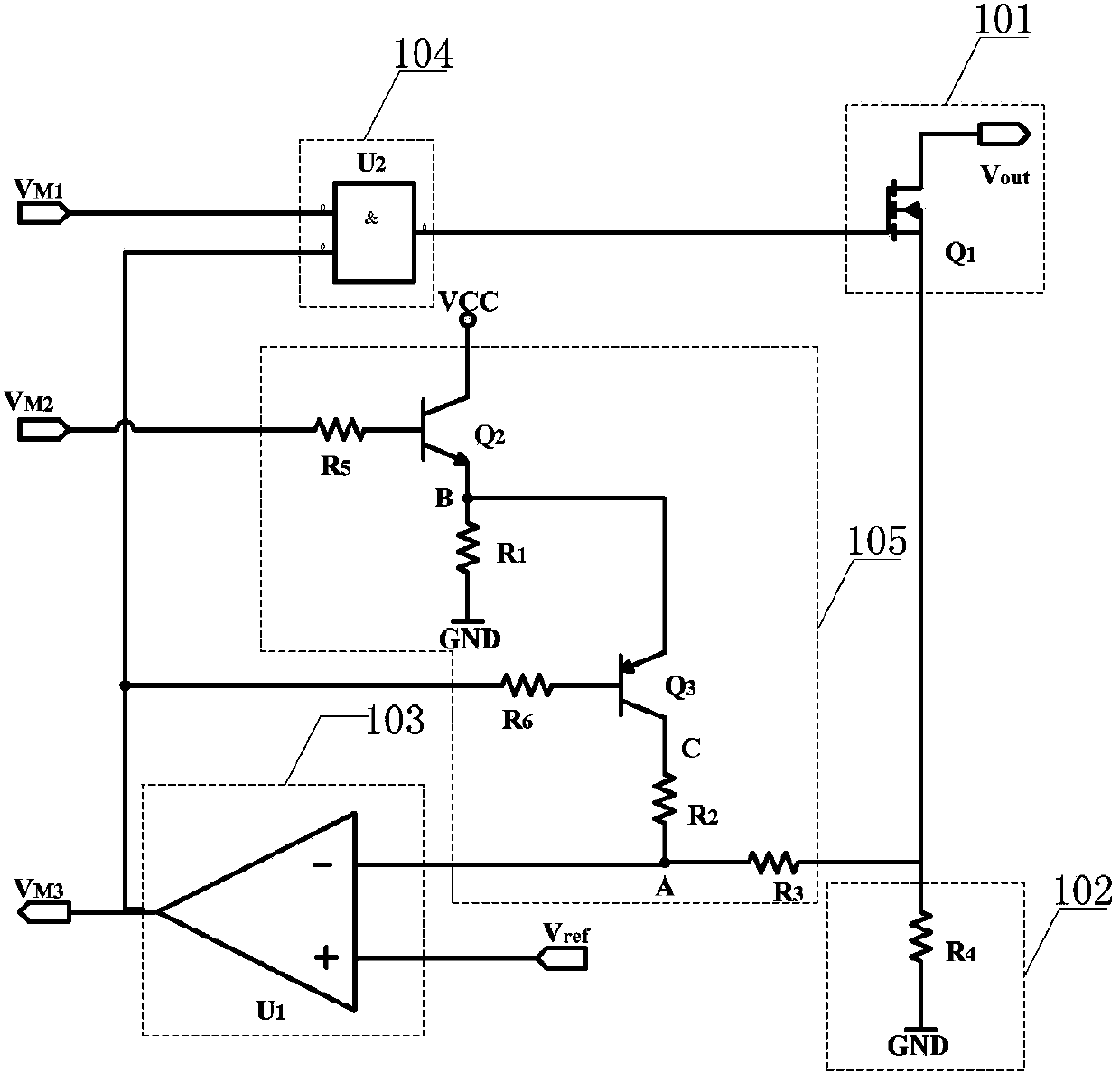
[0030] see figure 1 , is a schematic structural diagram of an overcurrent detection and protection circuit provided by an embodiment of the present invention, the circuit may include: a driving unit 101 , a sampling unit 102 , a signal generating unit 103 , a closing unit 104 and a holding unit 105 . in:

[0031] The driving unit 101 is used to drive the load circuit.

[0032] In this embodiment, the driving unit 101 may be a power transistor, and the power ...


PUM


Abstract

The invention provides an overcurrent detection and protection circuit which comprises a driving unit, a sampling unit, a signal generation unit, a closing unit and a maintaining unit, wherein the driving unit is used for driving a load circuit; the sampling unit is used for collecting currents in a loop of the load circuit; the signal generation unit is used for generating an overcurrent signal when the currents in the loop of the load circuit are larger than a preset value; the closing unit is used for closing the driving unit when the overcurrent signal is received; and the maintaining unit is used for maintaining a close state of the driving unit until a control signal sent by an MCU for starting the driving unit is received. According to the overcurrent detection and protection circuit, when the currents in the loop of the load circuit are detected to be larger than the preset value, the driving unit can be closed rapidly, the closed state is locked, and the circuit is protected.

Description

technical field [0001] The invention relates to the technical field of overcurrent protection, in particular to an overcurrent detection and protection circuit. Background technique [0002] Power tubes such as metal-oxide-semiconductor-field-effect transistor MOSFETs are used in drive circuits due to their many advantages such as large input impedance and small conduction voltage drop. However, when the current flowing through the MOSFET is too large, due to the existence of its internal resistance, it will cause excessive power and damage the device. [0003] To address the above problems, the prior art usually adopts the following solution: the current detection circuit detects the current flowing through the MOSFET, and when the current detected by the current detection circuit exceeds a set value, an overcurrent signal is sent to the Micro Control Unit (MCU). signal, the MCU turns off the MOSFET after receiving the overcurrent signal. [0004] The inventor found in th...

Claims


Application Information

Patent Timeline
Patent Type & Authority Applications(China)
IPC IPC(8): H02H3/08
Inventor 张淑颖陈志平
Owner BEIJING JINGWEI HIRAIN TECH CO INC
Why Eureka
Try Eureka