Over-current protection circuit of light-emitting diode (LED) constant-current driving circuit

An over-current protection circuit and constant-current drive technology, applied in over-current protection, lamp circuit layout, electric light source, etc., can solve problems affecting circuit performance, white light color shift, affecting luminous flux output, and luminous brightness Changes and other issues

Active Publication Date: 2013-04-10
OCEANS KING LIGHTING SCI&TECH CO LTD +1
View PDF2 Cites 5 Cited by
  • Summary
  • Abstract
  • Description
  • Claims
  • Application Information

AI Technical Summary

Problems solved by technology

However, this driving method also has many disadvantages: first, if the input voltage fluctuates slightly, it will directly lead to fluctuations in the driving current, thereby affecting the luminous flux output and the change in luminous brightness; second, the current limiting resistor connected in series It will consume a lot of power, especially when driving high-power LEDs, so the efficiency of the entire system will be a serious problem; finally, if the brightness of the LED is adjusted by adjusting the R value, the R value The change causes the current flowing through the LED to change, which will cause the color of the white light emitted by the LED to shift, so this driving method is mostly used in simple applications such as indicator lights.
[0005] Another protection method is to detect the current flowing through the switch tube, generally by connect...

Method used


Image

  • Over-current protection circuit of light-emitting diode (LED) constant-current driving circuit
  • Over-current protection circuit of light-emitting diode (LED) constant-current driving circuit
  • Over-current protection circuit of light-emitting diode (LED) constant-current driving circuit

Examples


Embodiment Construction

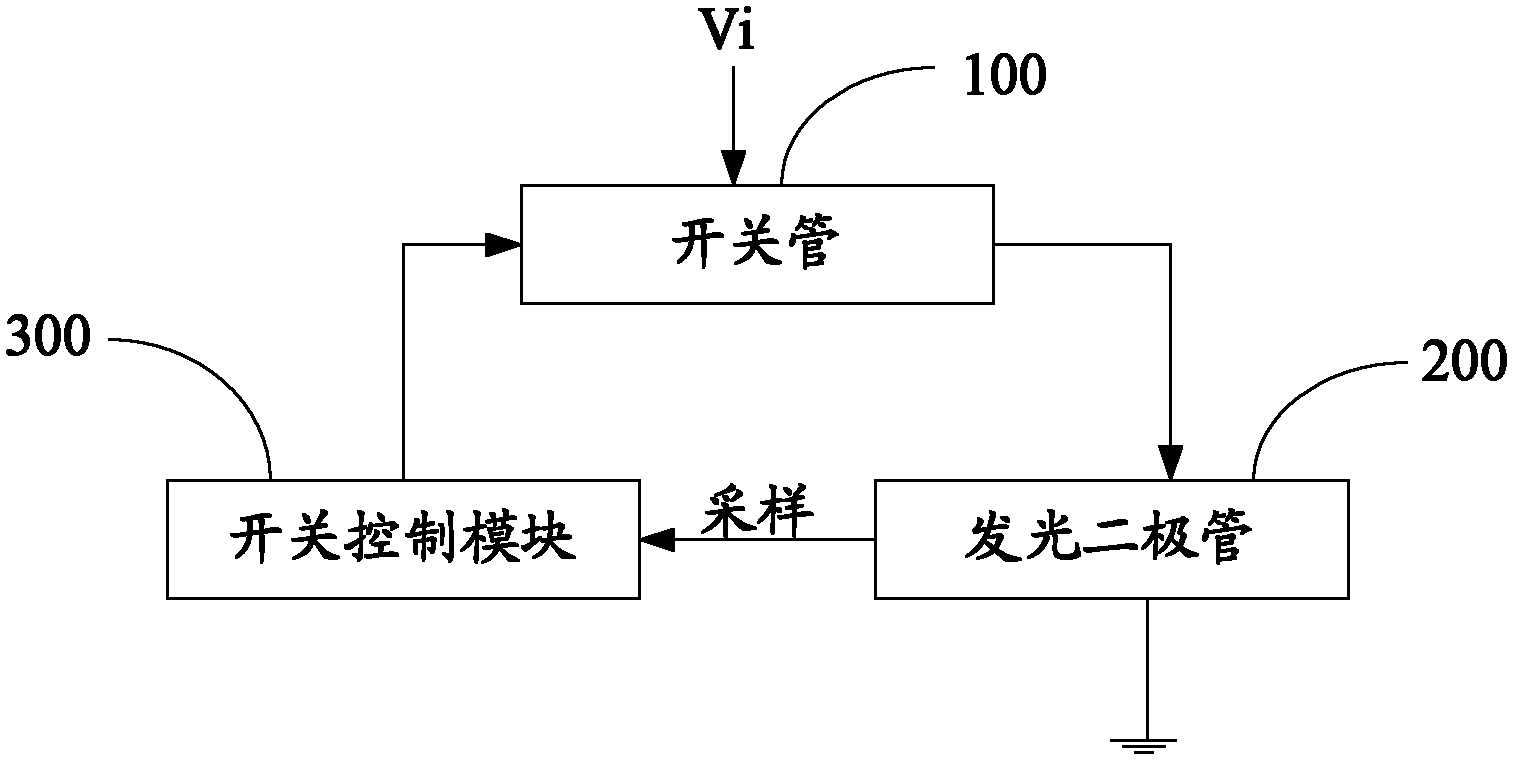
[0027] Such as figure 1 Shown is a schematic structural diagram of the overcurrent protection circuit of the LED constant current drive circuit. The overcurrent protection circuit of the LED constant current drive circuit is used for overcurrent protection of the constant current drive LED drive circuit. The overcurrent protection circuit includes a switch tube 100 connected in series with the light emitting diode 200. The switch tube 100 is a three-terminal switching device, including two access terminals and a control terminal. The switch tube 100 is connected in series with the light emitting diode 200 through two access terminals. catch.

[0028] The overcurrent protection circuit also includes a switch control module 300 , the input terminal of the switch control module 300 samples the working voltage of the LED 200 , and the output terminal is electrically connected to the control terminal of the switch tube 100 . The switch control module 300 controls the switching of...


PUM


Abstract

An over-current protection circuit of an LED constant-current driving circuit comprises an LED, a switching tube and a switching control module, wherein an output end of the switching tube is grounded after being electrically connected with the LED, an input end of the switching control module is electrically connected between the output end of the switching tube and the LED, an output end of the switching control module is electrically connected with a control end of the switching tube, and the switching control module is used for controlling the connection and the disconnection of the switching tube by controlling of the control end of the switching tube. The peak current of the LED is limited through the design method which is simple, clear and low in complexity, so that the LED is protected.

Description

【Technical field】 [0001] The invention relates to a protection circuit, in particular to an overcurrent protection circuit of an LED constant current drive circuit. 【Background technique】 [0002] During the working process of the LED constant current source driver, when the output load is too large, the internal components of the device or the external circuit have a partial short circuit, the overcurrent protection circuit can limit the current flowing through the switch tube, so that it can be controlled within the rated range within. [0003] There are two commonly used current limiting circuits: [0004] One is a resistor current-limiting circuit. In this way, the circuit is simple. By changing the value of the current-limiting resistor R, the operating current can be changed, thereby changing the luminous intensity of the LED (Light Emitting Diode). However, this driving method also has many disadvantages: first, if the input voltage fluctuates slightly, it will dire...

Claims


Application Information

Patent Timeline
IPC IPC(8): H05B37/02H02H3/08
Inventor 周明杰任义
Owner OCEANS KING LIGHTING SCI&TECH CO LTD
Why Eureka
Try Eureka