PFC (power factor correction) circuit
A circuit and control circuit technology, applied in the field of PFC, can solve the problem of low PF value, achieve the effect of eliminating the influence of PF value, solving the effect of low PF value, and weakening the influence of PF value
- Summary
- Abstract
- Description
- Claims
- Application Information
AI Technical Summary
Problems solved by technology
Method used
Image

Examples
Embodiment 1
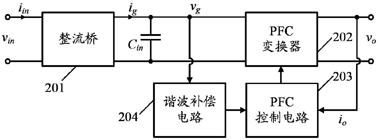
[0036] Such as figure 2 As shown, including: rectifier bridge 201, input capacitor C in , PFC converter 202, PFC control circuit 203 and harmonic compensation circuit 204; wherein, the input terminal of harmonic compensation circuit 204 is connected with the high voltage output terminal of rectifier bridge 201, and its output terminal is connected with the voltage sampling input terminal of PFC control circuit 203 connected, its ground terminal is grounded; and its corner frequency f c When it is 50Hz, the corresponding phase is -45°.
[0037] The specific working principle is:
[0038] When the corner frequency f of the harmonic compensation circuit 204c When V is 50Hz, the phase of the voltage at the output terminal of the harmonic compensation circuit 204 is higher than the DC input voltage v received at its input terminal g The phase lags 45°, that is, the AC input voltage v of the PFC circuit in The phase lag of 45°, since the output terminal of the harmonic compensa...
Embodiment 2
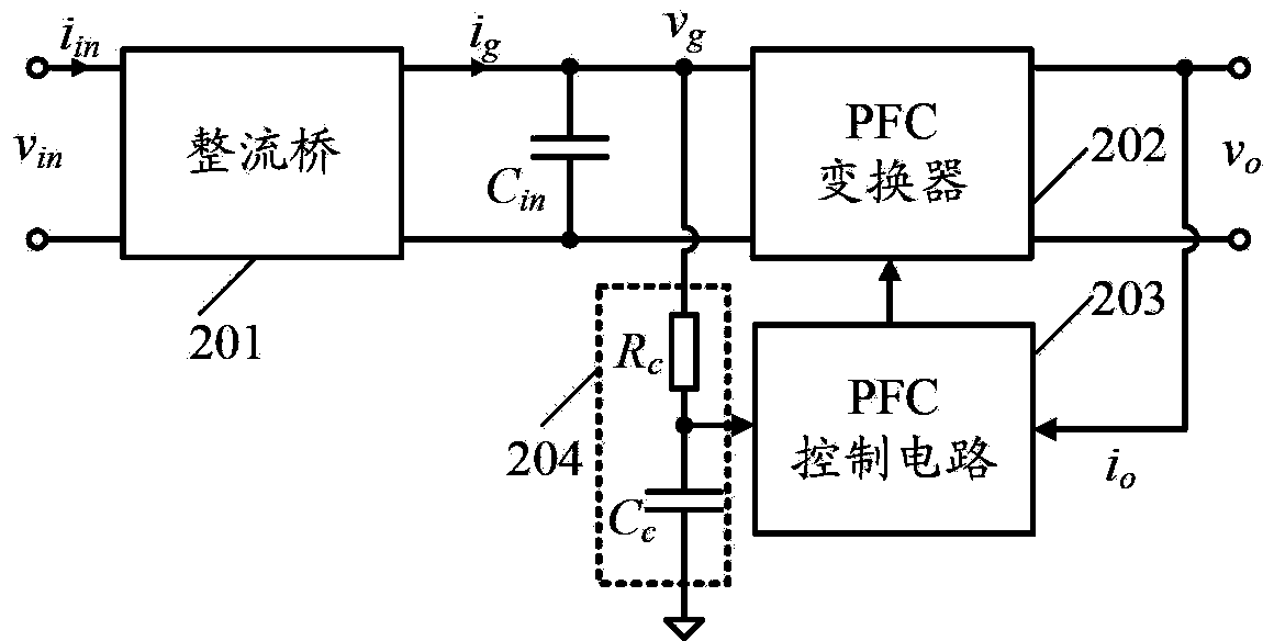
[0040] Such as image 3 As shown, including: rectifier bridge 201, input capacitor C in , PFC converter 202, PFC control circuit 203 and harmonic compensation circuit 204; wherein, the input terminal of harmonic compensation circuit 204 is connected with the high voltage output terminal of rectifier bridge 201, and its output terminal is connected with the voltage sampling input terminal of PFC control circuit 203 connected, its ground terminal is grounded; and its corner frequency f c When it is 50Hz, the corresponding phase is -45°.
[0041] The difference with the above-mentioned embodiment is:
[0042] The harmonic compensation circuit 204 includes: harmonic compensation resistors R connected in series c and harmonic compensation capacitor C c ; Among them, the harmonic compensation resistor R c with harmonic compensation capacitor C c The connection point of is used as the output end of the harmonic compensation circuit 204, and the harmonic compensation resistor R ...
Embodiment 3
[0047] Such as Figure 5 As shown, including: rectifier bridge 201, input capacitor C in , PFC converter 202, PFC control circuit 203 and harmonic compensation circuit 204; wherein, the input terminal of harmonic compensation circuit 204 is connected with the high voltage output terminal of rectifier bridge 201, and its output terminal is connected with the voltage sampling input terminal of PFC control circuit 203 connected, its ground terminal is grounded; and its corner frequency f c When it is 50Hz, the corresponding phase is -45°.
[0048] The difference with the above-mentioned embodiment is:
[0049] PFC control circuit 203 includes:
[0050] A voltage sampling circuit 2031, the input terminal of the voltage sampling circuit 2031 is the voltage sampling input terminal of the PFC control circuit 203;
[0051] A current sampling circuit 2032, the current sampling circuit 2032 is connected to the output end of the PFC converter 202;
[0052] Error signal amplification...
PUM
 Abstract
Description
Claims
Application Information