
A video switching circuit and switching method thereof

A technology of video switching and circuit, which is applied in the field of video switching circuit and its switching, can solve the problems of image transmission container interference, unclear image, etc., and achieve the effect of small digital switching interference, high image definition and high resolution

Active Publication Date: 2016-09-21
深圳聚融科技股份有限公司
View PDF4 Cites 0 Cited by
  • Summary
  • Abstract
  • Description
  • Claims
  • Application Information

AI Technical Summary

Problems solved by technology

[0005] The purpose of the present invention is to propose a video switching circuit, which can solve the problems that the image transmission container is disturbed and the image is not clear

Method used


Image

  • A video switching circuit and switching method thereof

Examples


Embodiment Construction

[0016] In the following, the present invention will be further described in conjunction with the drawings and specific embodiments.

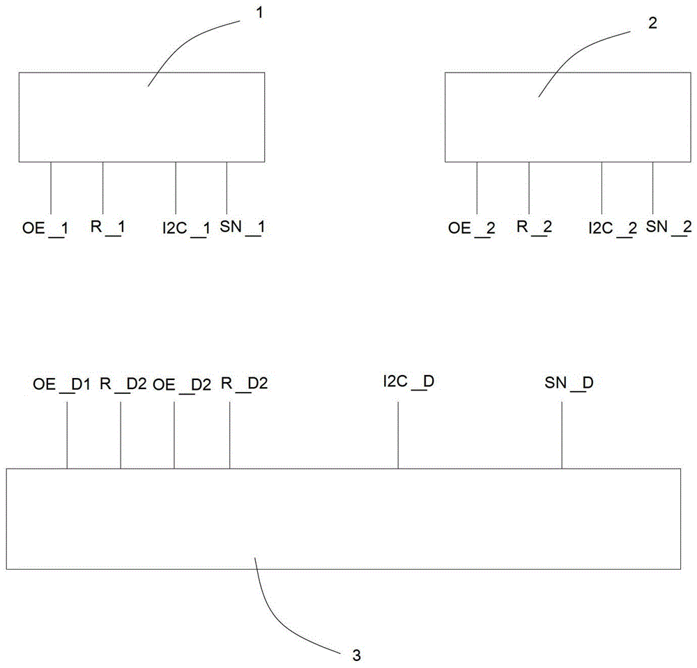
[0017] like figure 1 As shown, a video switching circuit includes an image sensor 1 , an image sensor 2 and a DSP processor 3 . The image sensor 1 has a high resistance pin OE_1, a reset pin R_1, an I2C bus pin I2C_1 and a data bus pin SN_1. The image sensor 2 has a high resistance pin OE_2, a reset pin R_2, an I2C bus pin I2C_2 and a data bus pin SN_2. The DSP processor has a first control IO port OE_D1, a first control IO port OE_D2, a second control IO port R_D1, a second control IO port R_D2, a data bus port SN_D, and an I2C bus port I2C_D. Of course, according to common knowledge in this field, the number of I2C bus pins I2C_1, I2C bus pins I2C_2 and I2C bus ports I2C_D is two, and the number of data bus pins SN_1, data bus pins SN_2 and data bus ports SN_D are equal. There are multiple and the three are equal in number.

[0018] The I2...


PUM


Abstract

Provided is a video switching circuit and method. The video switching circuit comprises a plurality of image sensors and a digital signal processor (DSP). Intel-IC (I2C) bus pins of the plurality of image sensors are connected in parallel and connected with an I2C bus port of the DSP. Data bus pins of the plurality of image sensors are connected in parallel and connected with a data bus port of the DSP. High-resistance pins of the plurality of image sensors are connected with a plurality of first control input / output (IO) ports of the DSP in a one-to-one corresponding mode, and reset pins of the plurality of image sensors are connected with a plurality of second control IO ports of the DSP in a one-to-one corresponding mode. The DSP is used for inputting low level to a high-resistance pin and a reset pin of one image sensor and inputting high level to high-resistance pins and reset pins of the other image sensors. By means of the video switching circuit and method, high-definition images with high resolution and good controllability can be obtained, and distortion caused by later processing and adjusting after the images are output by the DSP is repaired.

Description

technical field [0001] The invention relates to a video switching circuit and a switching method thereof. Background technique [0002] The current principle of image imaging and switching: 1. The image sensor senses light (ie, light signal) to generate electricity (ie, electrical signal). After AD conversion, the original data is transmitted to the DSP processor, and the DSP processor processes the electrical signal. After processing, the video signal is output to an output device (such as a monitor). When outputting a single video signal, a combined structure of a single image sensor + a single DSP processor is used. If the conversion of multiple video signals is involved, it is necessary to switch the analog video signal processed by the DSP processor, so that the video bus can obtain multiple different video signals in time. At present, the video bus can obtain multiple different video signals in time-sharing, and there are two ways: 1. Analog video signals are directl...

Claims


Application Information

Patent Timeline
Patent Type & Authority Patents(China)
IPC IPC(8): H04N5/268
Inventor 李皓
Owner 深圳聚融科技股份有限公司
Learn More