Separate-rod-source telescoping mechanism for PET-CT and control method thereof

A PET-CT and telescopic mechanism technology, applied in the field of medical devices, can solve the problems of high cost, high price and high cost, and achieve the effect of low conversion cost and simple structure

Active Publication Date: 2015-04-15
北京锐视康科技发展有限公司
View PDF7 Cites 0 Cited by
  • Summary
  • Abstract
  • Description
  • Claims
  • Application Information

AI Technical Summary

Problems solved by technology

At present, there are two kinds of structures commonly used, one is that the telescopic mechanism of the rod source rotates together with the rod source, and an external brush is used to supply power to the telescopic motor of the rod source; the other is that the telescopic mechanism does not rotate with the rod source, and is grasped by a manipulator. Both structures have the disadvantages of high cost, complex structure and relatively high failure rate.
In the development process of PET-CT, there are the following problems in the selection of the expansion and contraction scheme of the driving rod source: if the brush is used, the large-diameter brush in our country is not yet a very good mature product, and the foreign products are not available. The price is too high; if the robot is used, the cost is also very expensive

Method used


Image

  • Separate-rod-source telescoping mechanism for PET-CT and control method thereof
  • Separate-rod-source telescoping mechanism for PET-CT and control method thereof
  • Separate-rod-source telescoping mechanism for PET-CT and control method thereof

Examples


Embodiment Construction

[0025] The present invention will be further described through the embodiments below in conjunction with the accompanying drawings.

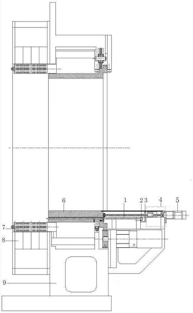
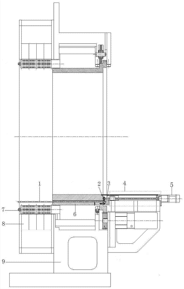
[0026] figure 1 with figure 2 Respectively, the cross-sectional views of the rod source retracted from the shield and extended from the shield. Such as figure 1 with figure 2 As shown, in the PET in PET-CT, the collimator ring 7 is set in the detector ring 8, the detector ring 8 is fixed on the frame 9, and the rod source 1 is set in the shielding body 6. When scanning, the rod The source 1 protrudes from the shield 6 in the collimator ring and scans around the detector.

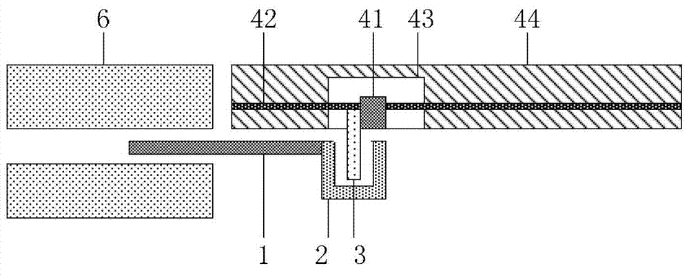
[0027] Such as figure 1 with 2 As shown, the PET-CT detachable rod source telescopic mechanism includes: a push-pull head 2, a paddle 3, a translation mechanism 4 and a motor 5; wherein, the push-pull head 2 is arranged at the end of the rod source 1; the translation mechanism 4 is arranged on the frame 9, located at the end of the rod source 1 and parallel to the rod...


PUM


Abstract

The invention discloses a separate-rod-source telescoping mechanism for PET-CT and a control method thereof. The separate-rod-source telescoping mechanism for PET-CT comprises a sliding head, a shift plate, a shifting mechanism and a motor. The sliding head is disposed at the tail end of a rod source. The shifting mechanism disposed on the frame locates behind the rod source and is parallel to the same. The shift plate is disposed at the front end of the shifting mechanism which is connected with the motor. The sliding head is in a channel shape with two open sides. The shift plate locates in a channel of the sliding head and can separate from the side. The sliding head and the shift plate are separable; the shifting mechanism driving the rod source to telescope is fixed; when the rod source needs to telescope, the shift plate locating in the sliding head contacts with the rod source and pushes the rod source to telescope; when the rod source rotates, the shift plate does not contact with the sliding head, and the rod source is not affected in rotation. The mechanism is low in cost of converting telescoping and rotating of the rod source and is simple in structure.

Description

technical field [0001] The invention relates to the field of medical devices, in particular to a PET-CT detachable rod source telescopic mechanism and a control method thereof. Background technique [0002] As the most advanced imaging technology in the field of biomedical engineering today, molecular medical imaging technology is the application of imaging methods to conduct qualitative and quantitative research on the biological processes in the living body at the cellular and molecular levels. Real-time, dynamic, in-vivo, non-invasive imaging technology for changes in the body. It is the key and core technology for researching targeted and specific molecular probes and therapeutic drugs. Multimodal molecular imaging technology can realize the complementary advantages of different imaging devices, making the obtained imaging results more accurate and reliable. Clinical practice has proved that multimodal molecular medical imaging equipment plays an important role in the ...

Claims


Application Information

Patent Timeline
Patent Type & Authority Patents(China)
IPC IPC(8): B25J18/04B25J9/16A61B6/03
Inventor 张跃明曾海宁邹捷张占军
Owner 北京锐视康科技发展有限公司
Why Eureka
Try Eureka