Spring strut bearing

A technology of struts and suspensions, applied in the direction of suspensions, elastic suspensions, shock absorbers, etc., can solve problems such as expensive and complex structures, and achieve a good sealing effect

Inactive Publication Date: 2007-12-19
SCHAEFFLER TECH AG & CO KG
View PDF3 Cites 2 Cited by
  • Summary
  • Abstract
  • Description
  • Claims
  • Application Information

AI Technical Summary

Problems solved by technology

Such an arrangement however has a complex construction and is therefore expensive

Method used


Image

  • Spring strut bearing

Examples


Embodiment Construction

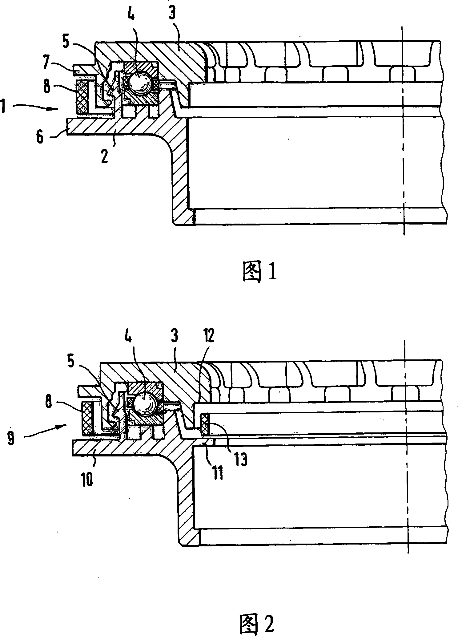
[0017] The suspension strut bearing 1 shown in FIG. 1 basically comprises a housing lower part 2 and a housing upper part 3 which together form a bearing housing in which an axial rolling bearing is accommodated 4. Housing lower part 2 and housing upper part 3 are connected to one another via a snap connection, the two housing parts forming a labyrinth seal 5 which prevents dirt, sand or moisture from penetrating into axial rolling bearing 4 .

[0018] In the region of the parting gap between the housing lower part 2 and the housing upper part 3, the housing parts 2, 3 each have a radial projection 6, 7 on which a sealing ring 8 is held. between.

[0019] The sealing ring 8 has a rectangular cross section and is arranged displaceably between the projections 6 , 7 . When the suspension strut is cleaned with a high-pressure water jet, the sealing ring 8 acts as a splash guard and prevents moisture or dirt from reaching the area of ​​the labyrinth seal 5 or from entering the in...


PUM


Abstract

The present invention relates to a suspension slide column support saddle which includes an axial sliding bearing or an axial rolling bearing, and the axial sliding bearing or axial rolling bearing is accommodated between a casing lower component and a casing upper component of a bearing casing; and at least one sealing element which seals the separation seam between the casing lower component and the casing upper component, wherein the sealing element is provided with at least one sealing ring (8, 13) which seals the separation seam between the inner circumference edge and the outer circumference edge of the bearing casing.

Description

technical field [0001] The invention relates to a suspension strut bearing (Federbeinlager) comprising an axial plain bearing or axial rolling bearing which is accommodated in a housing lower part and a shell of a bearing housing between the upper body part; and at least one sealing element sealing the separation seam between the lower housing part and the upper housing part. Background technique [0002] A suspension strut for a motor vehicle comprises a telescopic tube shock absorber and a helical spring with a large diameter, which is supported by a disc-shaped mount on the shock absorber and on the body mount of the motor vehicle. When the car turns, the suspension struts rotate around the piston rods of the shock absorbers. In order to reduce the resistance during steering, an axial plain bearing or an axial rolling bearing is arranged in the region of the bearing of the coil spring, said bearing mainly absorbing the axial weight and shock loads. [0003] A suspension...

Claims


Application Information

Patent Timeline
IPC IPC(8): B60G15/07F16F9/54
CPCF16C19/10B60G2204/1242B60G2206/73B60G2204/128B60G15/068B60G2204/61F16J15/4476B60G2204/124B60G2204/418F16C33/80B60G2206/8209F16C33/761B60G2204/43B60G2200/46B60G2204/44F16J15/441B60G2202/312F16C2326/05
Inventor R・卢茨C・施里克
Owner SCHAEFFLER TECH AG & CO KG
Why Eureka
Try Eureka