
Testing apparatus for mechanical grating ruling process

A technology of mechanical scribing and process testing, applied in diffraction grating, metal processing and other directions, can solve the problems of inability to set the installation angle, inability to adjust the levelness of the workpiece, and inability to monitor the three-way force.

Inactive Publication Date: 2013-11-20
CHANGCHUN UNIV OF SCI & TECH
View PDF6 Cites 14 Cited by
  • Summary
  • Abstract
  • Description
  • Claims
  • Application Information

AI Technical Summary

Problems solved by technology

Due to the limitation of the structural features of the system, the scoring tool has only one degree of freedom in the Z direction, and cannot rotate around the X, Y, and Z axes, and cannot realize the adjustment of the clamping angle of the scoring tool, or cannot set the installation angle; its positioning Although the platform has degrees of freedom in the X and Y directions, it cannot realize the level adjustment of the workpiece
In addition, its load signal detection unit can only detect the change of the force in the Z direction, and cannot monitor the entire marking process. three-way force Changes are monitored
Therefore, the micro-nano in-situ nano-indentation scribing test system is not suitable for the research of multi-degree-of-freedom and multi-directional load detection on the grating mechanical scribing process

Method used


Image

  • Testing apparatus for mechanical grating ruling process
  • Testing apparatus for mechanical grating ruling process
  • Testing apparatus for mechanical grating ruling process

Examples


Embodiment Construction

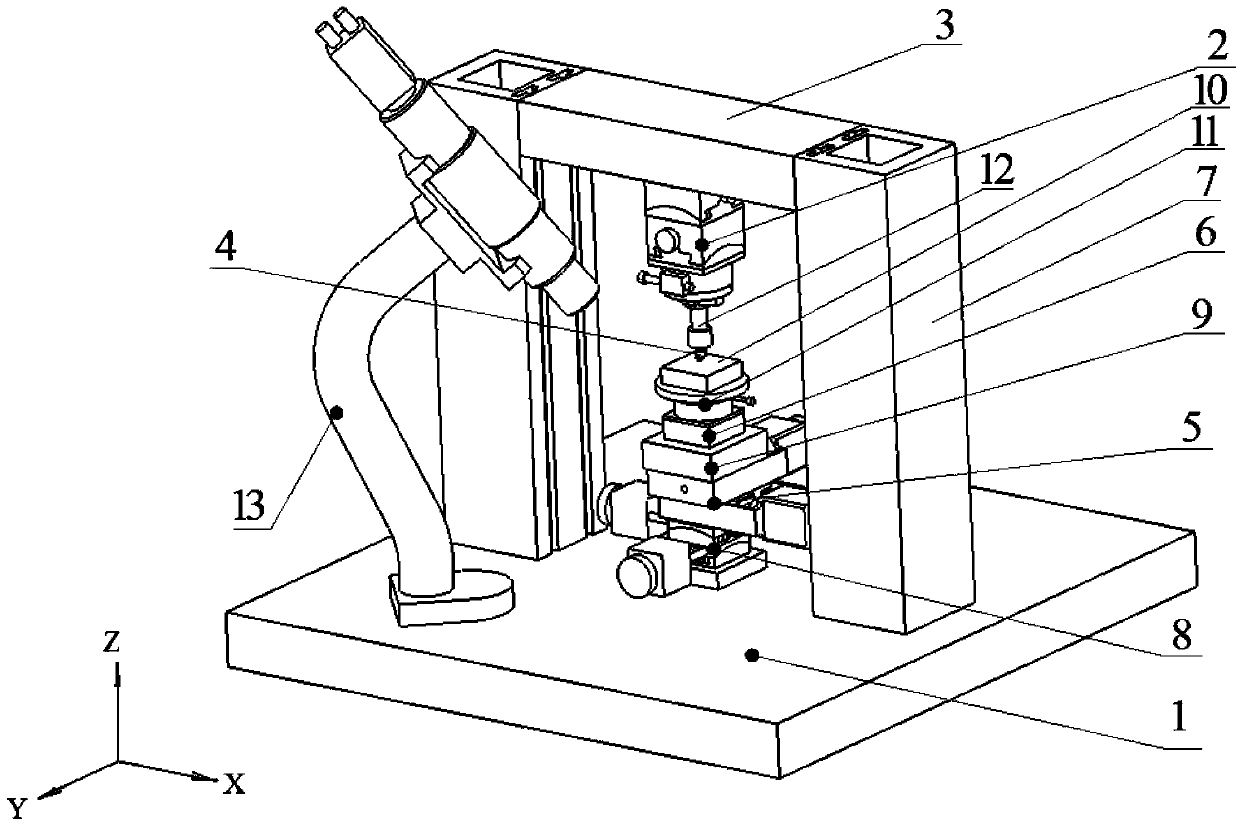
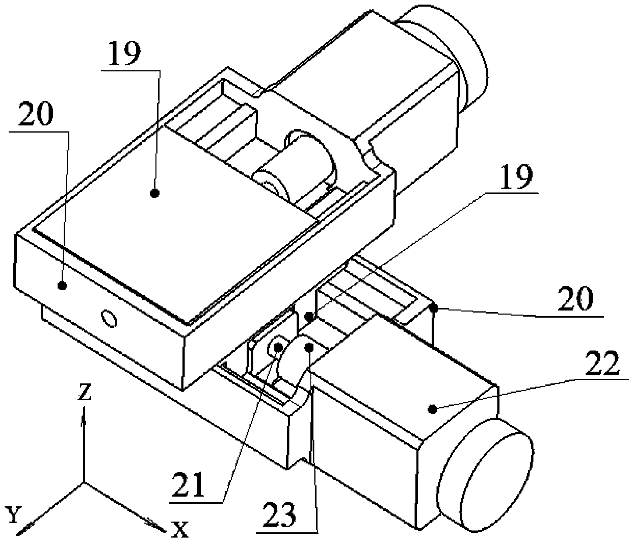
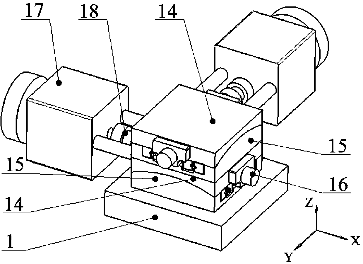
[0009] A grating mechanical scribing process test device, such as figure 1 As shown, the gantry suspension is installed on the base 1, and the knife rest 2 is rigidly suspended on the middle part of the gantry suspension crossbeam 3. Scoring cutter 4 is installed on knife rest 2 lower ends. The positioning platform corresponds to the tool rest 2 in the Z direction and is installed on the base 1 . The linear displacement platform 5 in the positioning platform is composed of the X-direction translation platform, the Y-direction translation platform, and the Z-direction translation platform 6. figure 1 , figure 2 shown. The two columns 7 of the gantry suspension are vertically fixed on the base 1, and the two ends of the beam 3 are connected with the inner sides of the two columns 7 through dovetail grooves. The arc displacement platform 8 in the positioning platform is formed by superimposing the X-axis arc displacement platform and the Y-axis arc displacement platform, s...


PUM


Abstract

The invention discloses a testing apparatus for a mechanical grating ruling process, belongs to the technical field of grating technologies and solves the problems that clamping angles of a ruling tool and levelness of a workpiece cannot be adjusted in the prior art. The testing apparatus is characterized in that a beam gantry is disposed on a base, and a tool rest is rigidly suspended on the middle of a cross beam of the beam gantry; the ruling tool is disposed at the lower end of the tool rest; a positioning platform corresponding to the tool rest in the Z direction is disposed on the base; a linear displacement platform in the positioning platform is formed by connecting an X-direction translation platform, a Y-direction translation platform and a Z-direction translation platform in a stacked manner; two columns of the beam gantry are vertically fixed on the base, and two ends of the cross beam are connected with the inner sides of the columns through dovetail grooves; an arc displacement platform in the positioning platform is formed by stacking an X-axis arc displacement platform and a Y-axis arc displacement platform; the linear displacement platform and the arc displacement platform are connected in a stacked manner; an XYZ-direction micro force dynamometer is positioned on the upper portion of the positioning platform; an X-axis adjusting seat, a Y-axis adjusting seat and a Z-axis adjusting seat are connected in a stacked manner.

Description

technical field [0001] The invention relates to a grating mechanical marking process test device, which belongs to the technical field of grating technology. Background technique [0002] Diffraction gratings, as the core devices in spectroscopic instruments, have been widely used in industry, national defense, scientific research and other fields. Compared with replication and holographic ion etching, grating mechanical scribing is a manufacturing process suitable for large-area, low-line density original diffraction gratings. This process should have high Scoring accuracy, thereby improving grating diffraction efficiency. [0003] A solution related to the grating mechanical scribing machine is "micro-nano in-situ nano-indentation scribing test system". The test system includes a precise positioning platform in the X and Y axis directions, a precise linear positioning platform in the Z axis direction, a precision press-in drive unit, a load signal detection unit, a displ...

Claims


Application Information

Patent Timeline
IPC IPC(8): B26D3/08B26D5/00G02B5/18
Inventor 石广丰史国权宋林森王磊肖为吕洋洋蔡宏彬丁健生胡明亮周锐奇
Owner CHANGCHUN UNIV OF SCI & TECH
Learn More