
Rolling cylinder transmission device

A transmission device, cylinder technology, applied in the direction of fluid transmission device, transmission device, belt/chain/gear, etc., can solve the problems of load leakage and pressure loss, work difficulties, personal and equipment damage, etc., and achieves low processing accuracy requirements, The effect of reducing motion friction and increasing fluidity

Inactive Publication Date: 2013-11-20
NANJING VOCATIONAL UNIV OF IND TECH
View PDF4 Cites 2 Cited by
  • Summary
  • Abstract
  • Description
  • Claims
  • Application Information

AI Technical Summary

Problems solved by technology

[0003] The current hydraulic and pneumatic transmission technology has obvious advantages in the size and direction of mechanical force and motion, especially in the transmission path of force and motion, but it also has obvious disadvantages: 1) It is difficult to achieve sealing The processing, installation precision and sealing requirements of components are very high; 2) Leakage and loss of pressure are prone to occur during long-term loads, resulting in system failure; Can cause pollution; 4) It is difficult to work under high temperature conditions

Method used


Image

  • Rolling cylinder transmission device
  • Rolling cylinder transmission device
  • Rolling cylinder transmission device

Examples


Embodiment Construction

[0016] The roller transmission device of the present invention will be described in detail below in conjunction with the accompanying drawings.

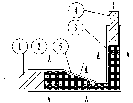
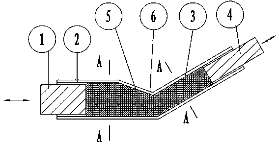
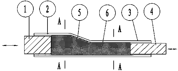
[0017] Such as figure 1 As shown, the roller transmission device of the present invention is composed of an input cylinder 1, an input piston 2, a variable section transition section 3, an output cylinder 4, an output piston 5, and a roller 6. The input cylinder 1, the input piston 2, the variable section transition section 3, the output cylinder 4 and the output piston 5 are made of metal or non-metal, and its cross section can be rectangular, and its width is equal to the length of the roller body 6 and is a gap Cooperate. The roller body 6 is made of metal or non-metal, and its cross-sectional shape can be circular or elliptical. It can adopt a hollow structure, or it can use two materials that are light inside and hard outside to make an inner and outer double-layer structure (such as Figure 5 shown), in addition, the roll...


PUM


Abstract

The invention discloses a rolling cylinder transmission device. The rolling cylinder transmission device comprises an input cylinder body, an input piston, a variable-cross-section transition section, an output cylinder body, an output piston and a rolling cylinder, wherein the input cylinder body is connected with the output cylinder body through the variable-cross-section transition section, one end of the input piston is arranged inside the input cylinder body, one end of the output piston is arranged inside the output cylinder body, and the rolling cylinder body is injected into the input cylinder body, the output cylinder body and the variable-cross-section transition section. The rolling cylinder transmission device is low in requirement for machining accuracy of the cylinder bodies and the pistons, and has the obvious advantages of being free of leakage, small in pollution, resistant against high temperature and the like.

Description

technical field [0001] The invention relates to a device for transmitting and transforming mechanical force and movement, in particular to a device for transmission using roller bodies. Background technique [0002] Various transmission technologies such as gears, racks, tooth chains, soft cables, electromagnetic, hydraulic, and pneumatic are widely used in mechanical equipment to realize the transmission and transformation of mechanical force and motion, among which hydraulic and pneumatic transmission technologies have been obtained in mechanical equipment. Wide range of applications. [0003] The current hydraulic and pneumatic transmission technology has obvious advantages in the size and direction of mechanical force and motion, especially in the transmission path of force and motion, but it also has obvious disadvantages: 1) It is difficult to achieve sealing The processing, installation precision and sealing requirements of components are very high; 2) Leakage an...

Claims


Application Information

Patent Timeline
IPC IPC(8): F16H43/00
Inventor 白顺科
Owner NANJING VOCATIONAL UNIV OF IND TECH
Learn More