
land cultivation implements

A land and equipment technology, applied in the field of land cultivation equipment, can solve the problems that the land is not evenly cultivated, the mud flow is not optimally guided, and the blockage cannot be prevented.

Active Publication Date: 2016-10-12
LEMKEN
View PDF8 Cites 1 Cited by
  • Summary
  • Abstract
  • Description
  • Claims
  • Application Information

AI Technical Summary

Problems solved by technology

[0004] The known solutions have the disadvantage that the ground is not evenly cultivated over the entire working width, blockages due to free space problems cannot be prevented and the mud flow (Bodenfluss) is not guided optimally

Method used


Image

  • land cultivation implements
  • land cultivation implements
  • land cultivation implements

Examples


Embodiment Construction

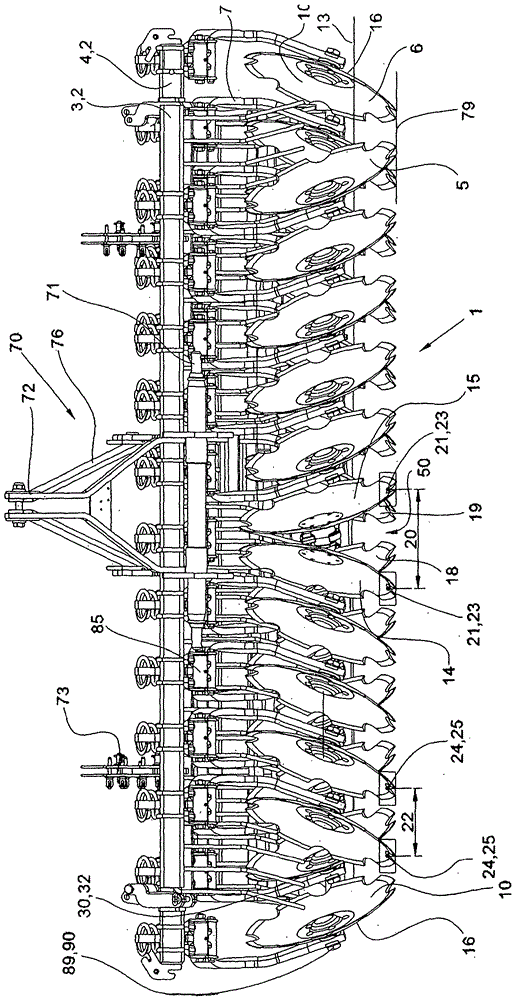
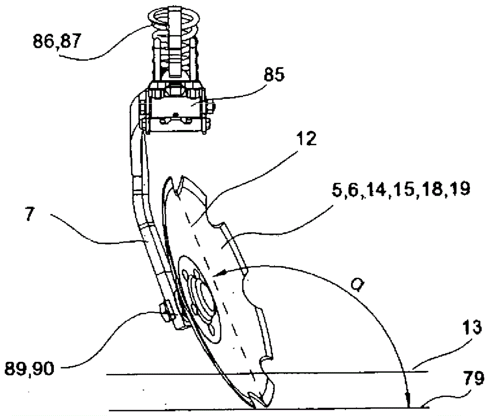
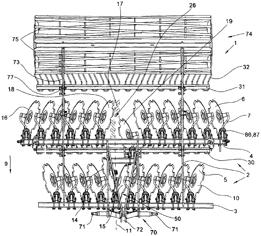
[0028] figure 1 A top view of the soil cultivation implement 1 is shown. The soil cultivation implement 1 can be a hooked, saddled or attached soil cultivation implement 1 . figure 1 An embodiment of an attached soil cultivation implement 1 is shown. A three-point tower (Dreipunktturm) 70 is used at the three-point linkage for attachment to a tractor, not shown. To this end, the three-point tower 70 has a lower link articulation point 71 and an upper link attachment point 72 . The three-point tower 70 is connected to the frame 2 comprising in particular the front frame part 3 and the rear frame part 4 . A hollow disk 5 is arranged on the front frame part 3 ; a hollow disk 6 is arranged on the rear frame part 4 . Viewed from the center 11 , the concave side 10 of the hollow disk 5 is directed obliquely forwards and outwards as viewed in the working direction 9 . The hollow disks 5 , ie the hollow disks 14 and 15 , are arranged in the center 11 or in the central region 50 i...


PUM


Abstract

The invention relates to a soil cultivation implement (1) having two tool rows of hollow disks (5, 6) with a first hollow disk row (5) and a second hollow disk row (6), in which the hollow disks Arranged with a slight rearward offset in the first hollow disk row. In the second hollow disk, the hollow disk is in a forwardly offset position. In order to avoid lateral tension in such a soil cultivating implement (1), the rows of hollow disks (5, 6) are arranged symmetrically and point towards each other with their convex sides (16) or with their concave sides (10). ) offset the hollow disk at the points where they point to each other. This offset leads to an optimization of the earth flow and prevents component collisions. This ensures even soil cultivation over the entire working width of the appliance ( 1 ), even in the region of greater working depth with hollow disks having a larger diameter.

Description

technical field [0001] The invention relates to a soil cultivating implement with a frame (Bodenbearbeitungsgerät) with two frame parts arranged one behind the other and arranged transversely, on which rotatably mounted hollow disks (Hohlscheibe) are arranged side by side, and the The hollow disks are connected to the frame part via carrier arms, wherein the hollow disks of the front frame part point obliquely forwards and outwards in the working direction with concave sides and the hollow disks of the rear frame part with concave sides In the working direction it points obliquely forwards and towards the center, wherein the concave side chords of the hollow disk enclose an obtuse angle with the ground surface. Background technique [0002] Such a soil tillage implement is known from US patent document US 1 944 275 . The object of this application is a towed soil cultivation implement with a frame having two frame parts, on which hollow disks with separate supports are arra...

Claims


Application Information

Patent Timeline
Patent Type & Authority Patents(China)
IPC IPC(8): A01B21/08
CPCA01B21/086A01B5/08A01B49/027
Inventor G.阿赫滕
Owner LEMKEN
Learn More