Riser support device under ultra-deep sea water

A support device and riser technology, applied in support devices, drilling equipment, earthwork drilling and production, etc., can solve the problems of increasing the construction and operation costs of floating production devices on the water surface, the applicability and economy of TTR risers, and increasing the water surface Problems such as the dynamic load of the floating production device can achieve the effect of simplifying the installation and dismantling process, reducing the construction cost and simplifying the difficulty of the construction process

Active Publication Date: 2013-08-21
DALIAN UNIV OF TECH
View PDF7 Cites 1 Cited by
  • Summary
  • Abstract
  • Description
  • Claims
  • Application Information

AI Technical Summary

Problems solved by technology

[0003] However, in the ultra-deep sea environment, the weight of the riser in the water will naturally increase sharply with the increase of water depth and water pressure; at the same time, the increase in the weight of the riser will also require a great increase in the tension at the top of the riser, which has great impact on the TTR standpipe. The applicability and economy of the tube pose serious problems
In addition, since the standpipe is connected to the surface floating production unit, as the water depth increases, the huge underwater riser load will increase the dynamic load that the water surface floating production unit must bear, thereby increasing the capacity of the water surface floating production unit. construction and operating costs
Therefore, using the traditional TTR riser production system, the overall production cost of the oil field is huge

Method used


Image

  • Riser support device under ultra-deep sea water
  • Riser support device under ultra-deep sea water
  • Riser support device under ultra-deep sea water

Examples


Embodiment Construction

[0023] The present invention will be further described below in conjunction with the accompanying drawings.

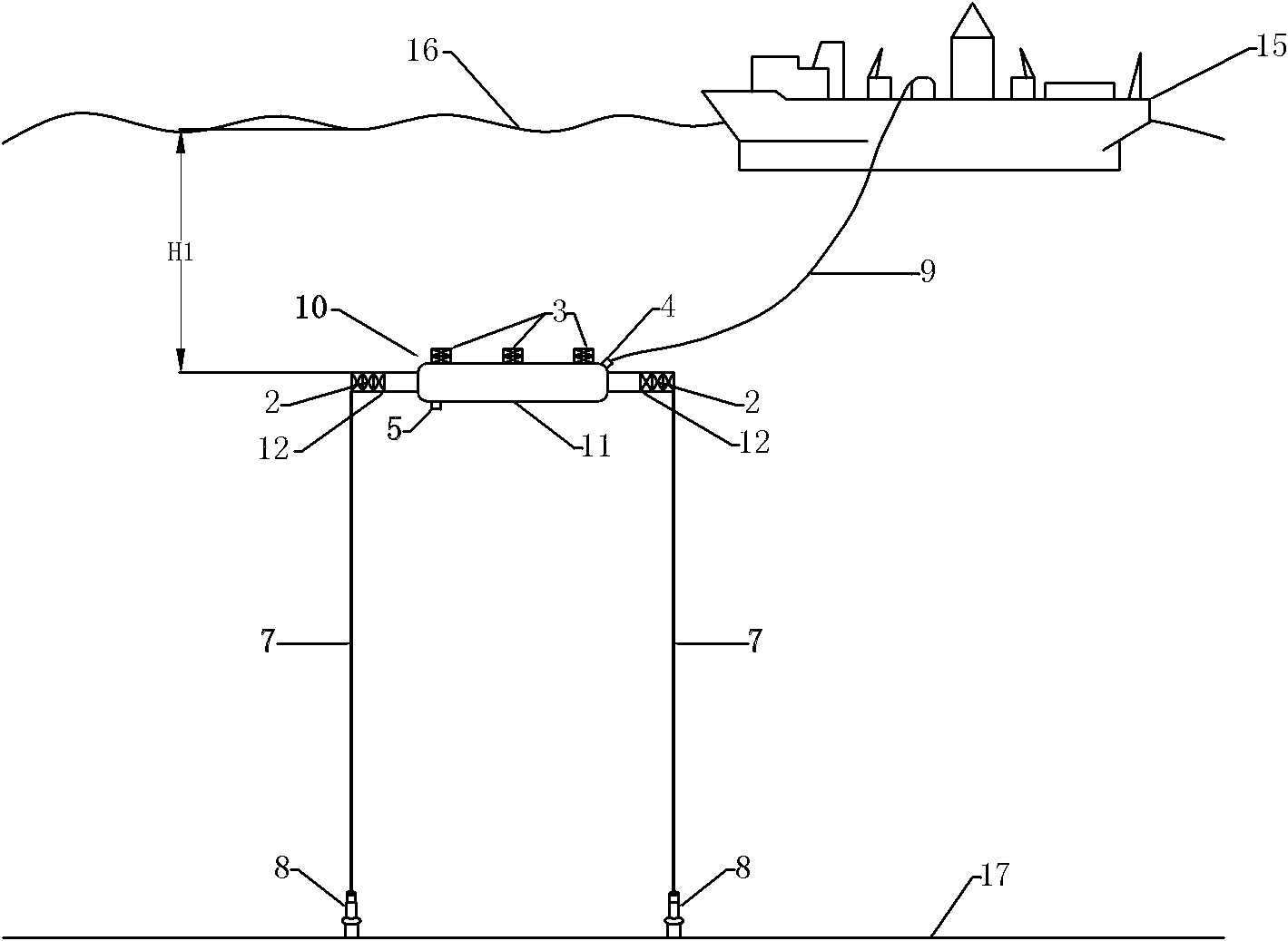
[0024] Such as figure 1 As shown, an ultra-deep sea underwater riser support device includes a riser support buoy 10, a tension mooring device and an umbilical cable 9.

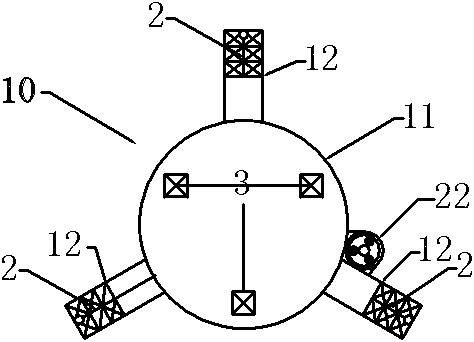
[0025] Such as Figure 1-2 As shown, the riser support buoy 10 is a starfish-like structure, that is, the central column structure buoy 11 is connected to three cantilever buoys 12 with a rectangular cross-section at the edge, and their included angle on the plane is 120°, forming a radial shape. The end of the cantilever buoy 12 adopts a neutrally buoyant truss structure 2 . When the design requires an additional increase in the buoyancy of the riser support buoy 10, it is only necessary to reduce the proportional length of the truss structure 2 on the cantilever buoy 12 or increase the length of the cantilever buoy 12; if the design buoyancy requirements are met, the truss can be increased The p...


PUM


Abstract

The invention discloses a riser support device under ultra-deep sea water. The device comprises a riser support buoy, a tension mooring device and an umbilical cable, wherein a wellhead A is formed on the upper part of the riser support buoy; a channel which passes through the riser support buoy is formed on the lower part of the wellhead A; and the riser support buoy has a starfish structure, namely the edge of a central post structure buoy is connected with three rectangular section cantilever buoys which form included angles of 120 degrees on the plane. The tail end of each cantilever buoyhas a truss structure with neutral buoyancy, so that the buoyancy requirement of the riser support buoy can be met by reducing or increasing the length of the truss structure on each cantilever buoy,the construction process difficulty of each cantilever buoy can be greatly reduced, and construction cost is reduced. The riser support buoy provides tension for a top tension riser (TTR), so that a dynamic load supported by a water surface floating production device is reduced, and the requirement on the water surface floating production device is reduced; therefore, the construction cost of thewater surface floating production device is reduced.

Description

technical field [0001] The invention relates to a deep sea oil and gas field development technology, in particular to an underwater riser support device used for the development of an ultra deep sea oil and gas field. Background technique [0002] As the only structure connecting the water surface part and the underwater production system, the riser is an important part of the development of offshore oil and gas fields, especially playing a key role in the development of deep sea and ultra-deep sea oil and gas fields. At present, the widely used and mature production riser in the field of deep sea petroleum engineering is the TTR riser, that is, the top tension riser. [0003] However, in the ultra-deep sea environment, the weight of the riser in the water will naturally increase sharply with the increase of water depth and water pressure; at the same time, the increase in the weight of the riser will also require a great increase in the tension at the top of the riser, whic...

Claims


Application Information

Patent Timeline
Patent Type & Authority Patents(China)
IPC IPC(8): E21B15/02
Inventor 黄一甄兴伟张崎刘刚李红霞
Owner DALIAN UNIV OF TECH
Why Eureka
Try Eureka