Electric hand drill with drill bit cooling function

A hand electric drill and drill bit technology, used in drilling/drilling equipment, manufacturing tools, portable drilling rigs, etc., can solve the problems of large impact on the life of the drill bit and poor cooling effect of the drill bit, so as to ensure the effective working depth and reduce the vibration sense. , the effect of improving the comfort of use

Inactive Publication Date: 2019-08-23
陈烁
View PDF8 Cites 2 Cited by
  • Summary
  • Abstract
  • Description
  • Claims
  • Application Information

AI Technical Summary

Problems solved by technology

[0004] The object of the present invention is to provide a kind of electric hand drill with drill bit cooling function, to solve the problem that the electric hand drill propos

Method used


Image

  • Electric hand drill with drill bit cooling function
  • Electric hand drill with drill bit cooling function
  • Electric hand drill with drill bit cooling function

Examples


Embodiment

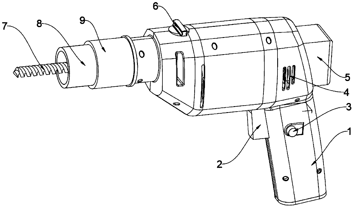
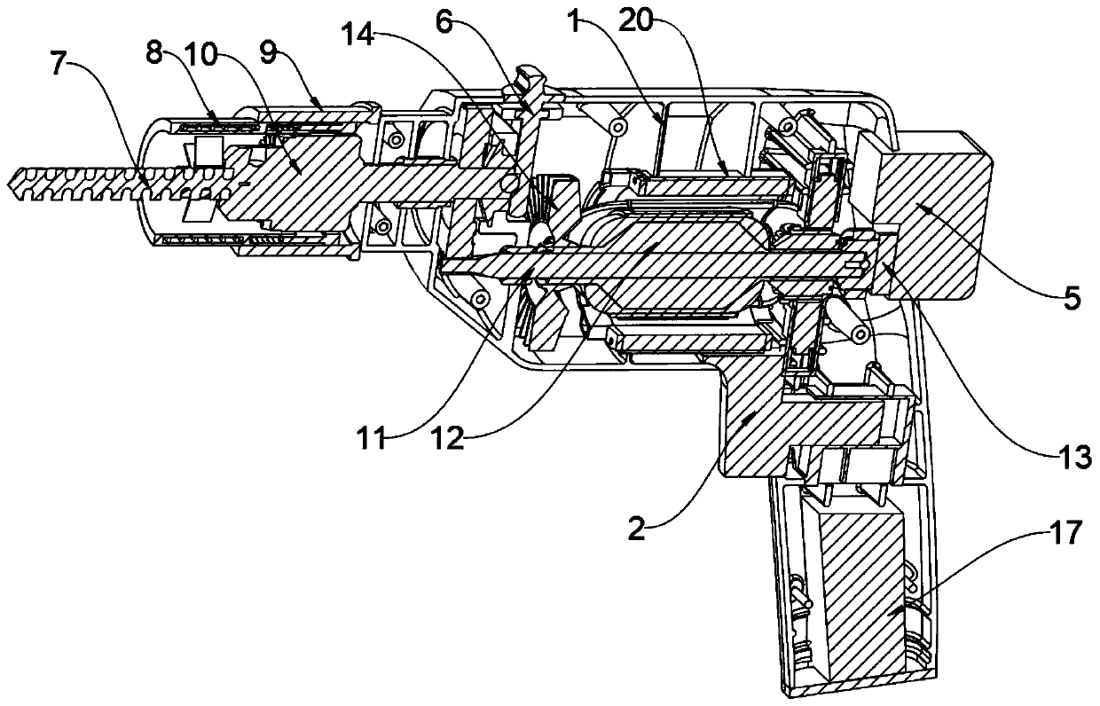
[0030] Example 1: See Figure 1-4 , an embodiment provided by the present invention: a hand electric drill with a drill bit cooling function, including a bottom cover 18, a battery 17 is installed on the lower end surface of the bottom cover 18, a battery limiting plate 19 is installed above the battery 17, and the battery limiting A switch 2 is installed on the top of the bit plate 19, a reverse button 3 is installed on the front end of the switch 2, a housing 1 is installed on the outside of the switch 2, a heat dissipation port 4 is installed on the front end of the housing 1, and the inside of the heat dissipation port 4 is installed. Connection box 13 is arranged, and water tank 5 is installed on one end of connection box 13, and motor shaft 11 is installed on the other end of connection box 13, and motor 12 is installed on the outside of motor shaft 11, and buffer pad 20 is installed on the outside of motor 12, and motor 12 Radiating blades 14 are installed on one side, ...

Embodiment 2

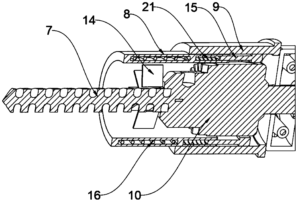
[0044] Embodiment 2: In this embodiment, the spiral winding mode of the spiral water pipe outside the water pipe sleeve 8 is added. In addition, the spiral water pipe is made of easy plastic material, and a spiral water pipe is respectively arranged on the two connecting pipes of the water tank 5. The airbag, the outlet and the inlet of the airbag are in a state of natural contraction when they are not connected. The specific working process of this embodiment is as follows:

[0045] The helical winding method makes the water pipe sleeve 8 move inside the continuous damping of the main sleeve 9, which effectively ensures the effective working depth of the drill bit and ensures the uniformity of the drill bit. In addition, the helical winding method is similar to The compression of the spring, during the working process of the drill bit, the heat generated and the compression of the water pipe itself make the air and water in it partially extruded, causing the pressure in the ai...


PUM


Abstract

The invention discloses an electric hand drill with a drill bit cooling function. The electric hand drill comprises a bottom cover. A battery is installed on the lower end face of the bottom cover. Abattery limiting plate is installed above the battery. A switch is installed above the battery limiting plate. A reverse rotation button is installed on the front end face of the switch. A shell is installed outside the switch. Cooling openings are formed in the front end face of the shell. A connection box is installed inside the cooling openings. A water tank is installed at one end of the connection box, and a motor shaft is installed at the other end of the connection box. A motor is installed outside the motor shaft. A buffer cushion is installed outside the motor. According to the electric hand drill, by arranging circulating water flow and blades outside a drill bit to conduct cooling, it is ensured that the temperature of the drill bit cannot be too high, and the temperature of water is controlled by the blades to a certain extent; and by additionally arranging the buffer cushion, the vibration feeling caused to the whole electric hand drill when the motor works is reduced, andthe use comfort degree is increased.

Description

technical field [0001] The invention relates to the technical field of electric hand drills, in particular to an electric hand drill with a drill bit cooling function. Background technique [0002] With the rapid development of social economy, electric hand drills are often used in daily life. Electric hand drills are drilling tools powered by AC power or DC batteries. The product with the largest sales volume is widely used in construction, decoration and furniture industries. At present, the performance of hand drills is getting better and better. but, [0003] The cooling effect of the existing electric drill is not good for the drill bit, and the water spray has a great influence on the life of the drill bit; In the technology, there are some electric hand drills that use water cooling to cool the drill bit: CN203197313U, CN202506871U, but the water cooling pipe can only be attached to the electric drill display, and cannot perform effective three-dimensional heat exch...

Claims


Application Information

Patent Timeline
IPC IPC(8): B23B45/02B23Q11/10B25F5/00
CPCB23B45/003B23B45/02B23Q11/1092B25F5/006
Inventor 陈烁
Owner 陈烁
Why Eureka
Try Eureka