Defoaming method and defoaming device

A defoaming device and defoaming technology, applied in separation methods, chemical instruments and methods, packaging, etc., can solve problems such as inability to improve defoaming performance, decrease in laser light concentration, and decrease in defoaming efficiency, and achieve energy attenuation Reduction, improvement of energy utilization efficiency, and pollution prevention effect

Active Publication Date: 2013-11-20
TOYO SEIKAN GRP HLDG LTD
View PDF4 Cites 8 Cited by
  • Summary
  • Abstract
  • Description
  • Claims
  • Application Information

AI Technical Summary

Problems solved by technology

[0010] However, such a large impact on the surface of liquids such as beverages will cause droplets to splash and adhere to the device or the condensing optical system such as the condensing lens, etc., causing contamination.
[0011] Therefore, in order to prevent the condensing optical systems such as the laser oscillator, the condensing lens, etc. from being polluted by the steam from the liquid surface, the foam point of the broken foam, etc., the position of the above-mentioned condensing optical system must be kept away from the above-mentioned liquid surface, resulting in Defoaming performance cannot be improved due to the decrease of the light concentration of the laser
[0012] In this way, the defoaming technology of Patent Document 2 proposed by the applicant is a better technology than previous defoaming technologies such as Patent Document 1, but according to subsequent research, it is found that there is still room for improvement in the following aspects: 1. The pulsed laser is irradiated on the surface of the liquid, and the focal length of optical elements such as lenses must be lengthened in order to avoid contamination by vapor from the liquid surface and foam points generated by burst foam. Improvement, 2. Pulse-shaped sound waves are generated in free space and propagate in the form of spherical waves. Only part of the above-mentioned pulse-shaped sound waves participate in the defoaming, so the defoaming efficiency decreases, so improvement is still needed to improve the above-mentioned defoaming efficiency

Method used


Image

  • Defoaming method and defoaming device
  • Defoaming method and defoaming device
  • Defoaming method and defoaming device

Examples


Embodiment approach

[0063] Figure 4 Another embodiment of the present invention is shown.

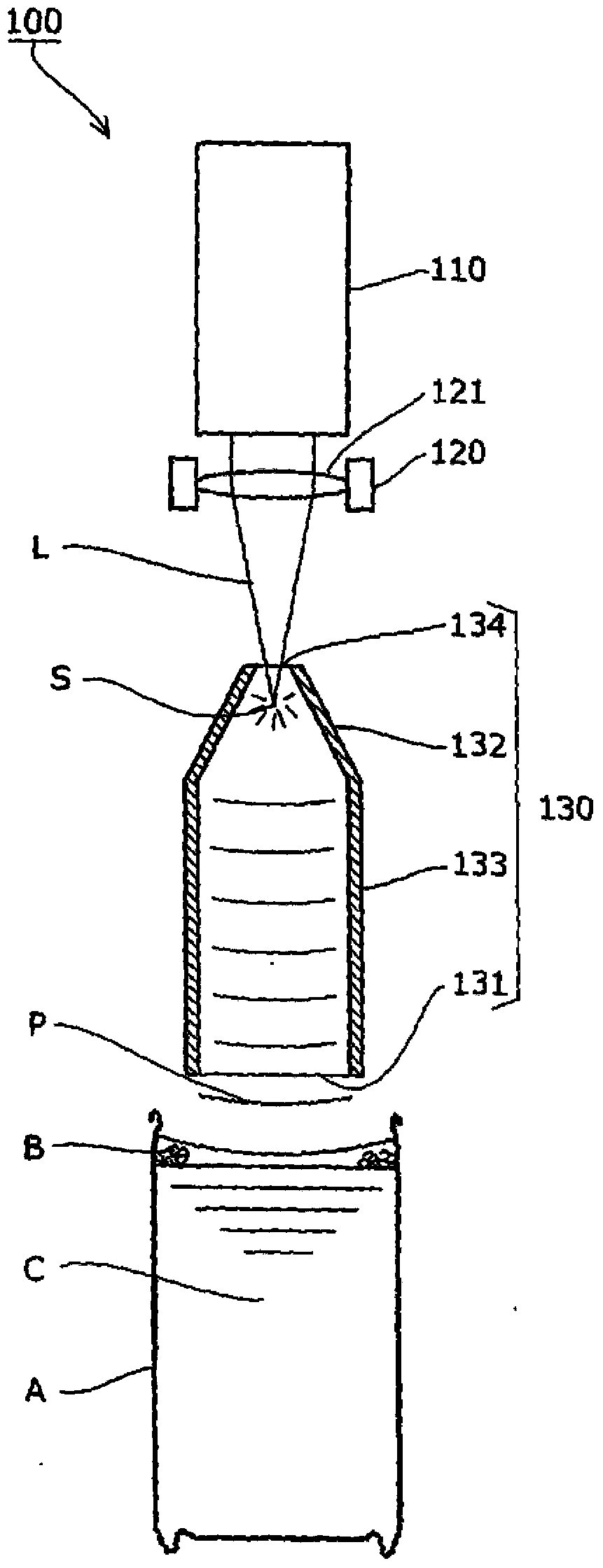
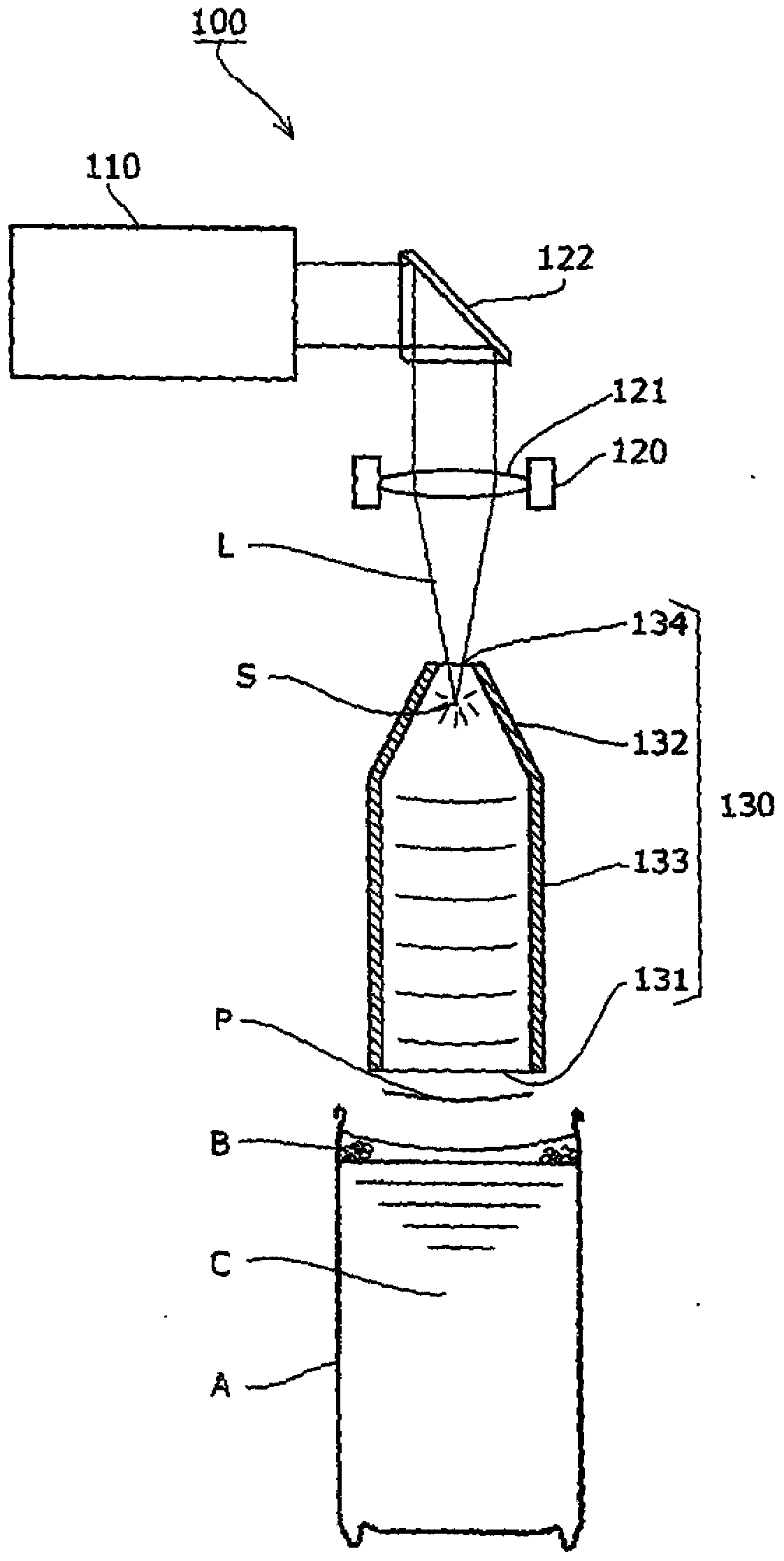
[0064]In this embodiment, the laser incident hole 234 is provided on the side of the tapered portion 232 of the acoustic waveguide 230, the pulse-shaped laser oscillation device 210 and the focusing optical system 220 are provided on the side, and the pulse-shaped laser light L is transmitted from the The light is illuminated from the side and concentrated toward the focal point S.

[0065] In addition, by providing the rear reflective wall 235 on the side opposite to the opening than the focal point S of the acoustic waveguide 230, the pulse-shaped sound wave P traveling from the focal point S in the direction opposite to the opening is directed toward the acoustic wave P by the rear reflective wall 235. The direction of the opening 231 is reflected and utilized as energy for defoaming.

[0066] Thereby, the utilization efficiency of energy improves further, and even if it is a low laser output, defoam...


PUM

PropertyMeasurementUnit
lengthaaaaaaaaaa

Abstract

The objective of the present invention is to obtain an effective defoaming effect by directing a pulsed sound wave generated by shock caused by laser-induced breakdown to a liquid surface using an acoustic waveguide. A reflected wave of the pulsed sound wave generated by shock caused by laser-induced breakdown on an inner circumference face of the acoustic waveguide is directed to an opening part of the acoustic waveguide opposed to the liquid surface, and variations in periods of time in which the reflected wave in each travelling direction arrives at the opening part are reduced.

Description

technical field [0001] The invention of the present application relates to the elimination of foam on the surface of a liquid, and in particular to the elimination of the foam produced when filling various containers such as metal cans, plastic cups, tray-shaped containers, PET bottles, cans, or glass bottles with contents such as beverages. Foam defoaming method and defoaming device. Background technique [0002] In the filling process of beverages (canned beverages, PET bottled beverages, bottled beverages, etc.) in various containers, the vertical container is usually filled with beverages from above in a filling machine, and then sealed with a sealing device (folding machine, press, etc.). capping machines, etc.) are sealed by caps or caps. In addition, as an important factor for maintaining the quality of beverages and improving the taste, there are cases where reducing the amount of residual oxygen in the airtight container, in particular, removing oxygen from the hea...

Claims


Application Information

Patent Timeline
Patent Type & Authority Applications(China)
IPC IPC(8): B01D19/02B65B3/22B67C3/22
CPCB67C3/22B01D19/02B01D19/0073B65B3/22G10K15/046
Inventor 辰见荣隆木村義彦中根佑也森田佳之
Owner TOYO SEIKAN GRP HLDG LTD
Why Eureka
Try Eureka