Surgical light and method for illuminating a surgical site

A technique of surgery and surgery, applied in the field of surgical operating lights

Active Publication Date: 2013-11-20
TRUMPF MEDIZIA SYST GMBH CO KG
View PDF5 Cites 18 Cited by
  • Summary
  • Abstract
  • Description
  • Claims
  • Application Information

AI Technical Summary

Problems solved by technology

Therefore, only the illuminance is adjusted without adjusting the light field diameter, because the light source in this sy...

Method used


Image

  • Surgical light and method for illuminating a surgical site
  • Surgical light and method for illuminating a surgical site
  • Surgical light and method for illuminating a surgical site

Examples


Embodiment Construction

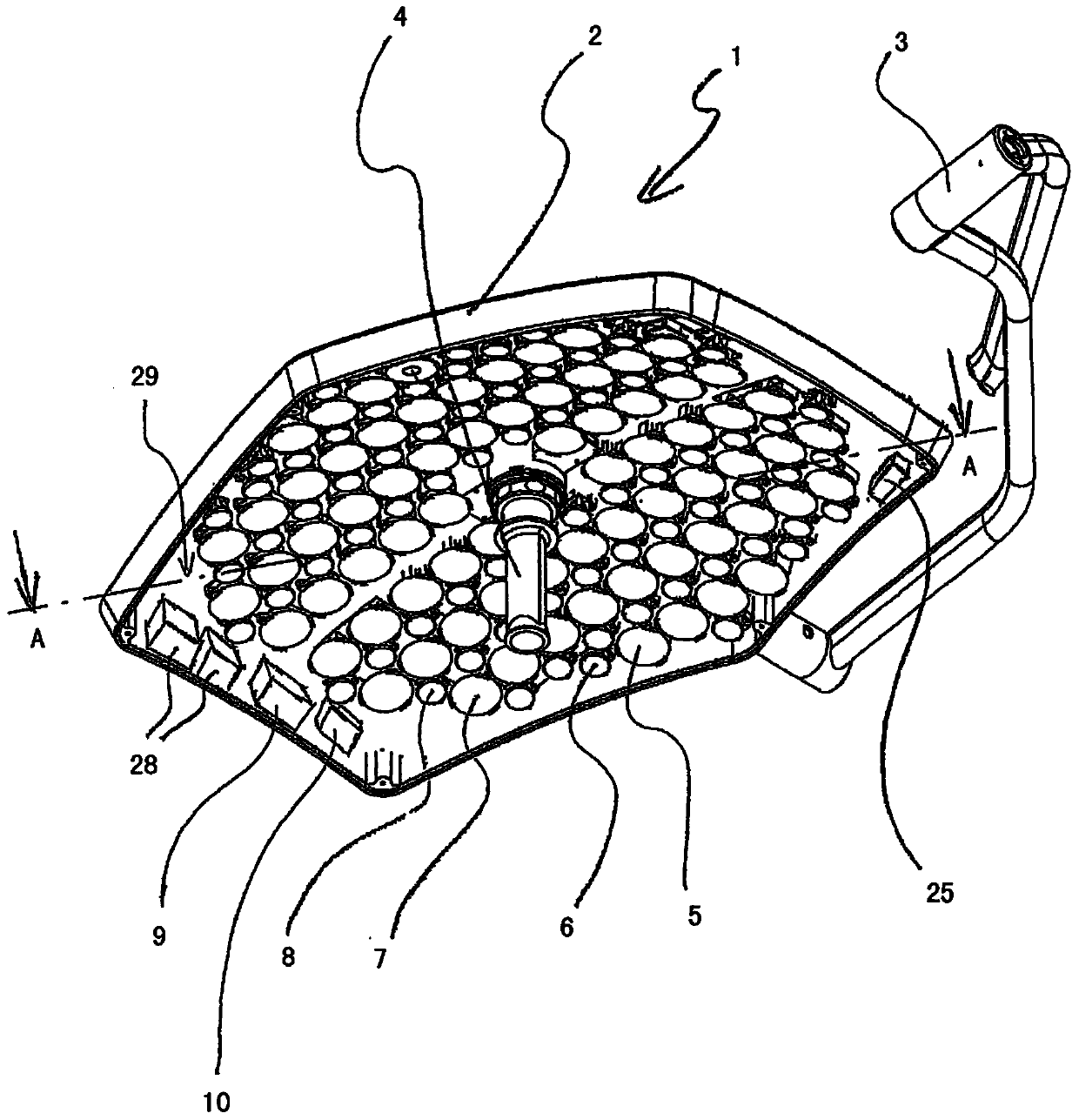
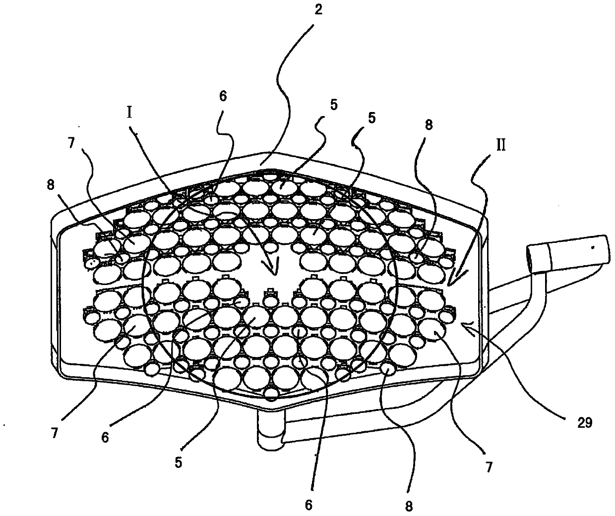
[0027] figure 1 A first exemplary embodiment of a surgical light 1 with a light body 2 and a carrier system 3 is shown, wherein only the so-called supporting rockers (Komfortbügel) and the so-called four-part rockers (Viertelbügels) of the carrier system 3 are shown. part. The handle 4 is arranged on the lamp body 2 , here in the center of the lamp body 2 . In an alternative embodiment, the handle 4 can also be arranged at other positions on the lamp body. The first light source 5 , the second light source 6 , the third light source 7 and the fourth light source 8 are arranged in the lamp body 2 . In addition, the light body 2 accommodates a control device 9, wherein in an alternative embodiment the control device 9 can be arranged in a separate housing and / or at another location on the surgical light or at the periphery of the surgical light middle.

[0028] In addition, means 25 for triggering changes in the individual light intensities of the light sources are provide...


PUM


Abstract

The operating light (1) has a lighting fixture (2) with an optical axis, which has two light sources (5,6), where a control device (9) is accommodated during a subsequent change of the selected distance between the lighting fixture and the operation area. The luminosities of the individual light sources are individually controlled such that the diameter on the operation area remains unchanged. An independent claim is also included for a method for operating an operating light.

Description

technical field [0001] The invention relates to a surgical light, in particular a surgical light for providing a light field whose light field diameter does not change when the working distance changes. Background technique [0002] Good lighting of the surgical field is necessary, among other factors, to allow the surgeon to operate in good conditions. This is usually accomplished by adjusting various parameters of the surgical light. Therefore, the position and direction of the lamp body, the focus of the light beam to the surgical site, and the light intensity of the outgoing light (ie, the illuminance at the surgical site) are usually adjustable. Changing the position and orientation as well as the light field is usually performed by the surgeon himself, whereby the surgeon holds the light body at a sterile handle attached to the light body and turns it to the desired position and desired orientation. By twisting the sterile handle, the distance between the merging of ...

Claims


Application Information

Patent Timeline
IPC IPC(8): F21S8/00F21V14/02F21V23/04A61B19/00F21V5/04F21V21/30F21V21/40F21W131/205F21Y101/02F21Y113/00
CPCF21Y2113/005F21Y2105/001F21V21/30F21V5/048A61B19/5202F21W2131/205A61B2019/461A61B2017/00106A61B2017/00057F21V14/02F21V23/0442F21Y2101/02F21S2/005F21S8/06F21V21/403A61B90/36A61B90/30A61B2090/061F21Y2105/10F21Y2115/10F21Y2113/13A61B90/35A61B17/52A61B1/0625
Inventor R·玛尔卡R·罗森海默尔
Owner TRUMPF MEDIZIA SYST GMBH CO KG
Why Eureka
Try Eureka