Make-up oil in refrigeration circuits

A refrigeration circuit and oil replenishment technology, applied in refrigerators, refrigeration components, refrigeration and liquefaction, etc., can solve problems such as damage to compressors and oil exhaustion

Active Publication Date: 2016-08-10
CARRIER CORP
View PDF6 Cites 0 Cited by
  • Summary
  • Abstract
  • Description
  • Claims
  • Application Information

AI Technical Summary

Problems solved by technology

This transfer of oil between said compressors may cause one or more compressors to be completely depleted of oil, which may severely damage the corresponding compressor

Method used


Image

  • Make-up oil in refrigeration circuits
  • Make-up oil in refrigeration circuits
  • Make-up oil in refrigeration circuits

Examples


Embodiment Construction

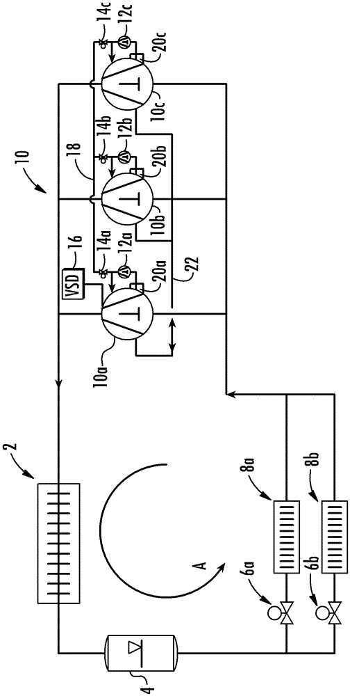
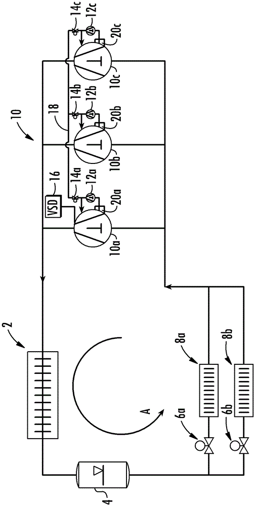
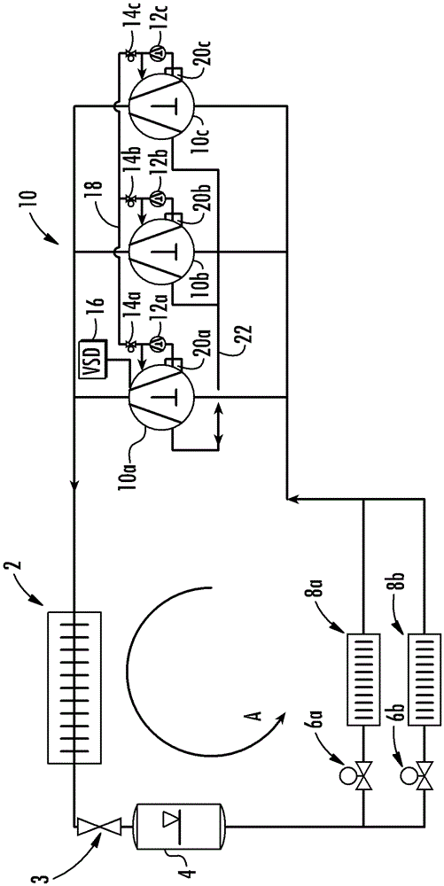
[0011] figure 1 A schematic diagram of a refrigeration circuit configured to circulate refrigerant in a counterclockwise direction as indicated by arrow A is shown. The refrigeration circuit comprises, in the direction of flow of the refrigerant: a heat rejection heat exchanger 2 configured to cool the refrigerant; a receiver 4 configured to storage refrigerant; a pair of expansion devices 6a, 6b configured to expand the circulating refrigerant, i.e. to reduce the pressure of the refrigerant; and two evaporators 8a, 8b, the The evaporators are arranged downstream of the expansion devices 6a, 6b, respectively, and are configured for heating and evaporating the expanded refrigerant.

[0012] Although in figure 1 In the exemplary embodiment shown, two expansion devices 6a, 6b and two evaporators 8a, 8b are connected in parallel, but it will be clear to a person skilled in the art that any number of expansion devices 6a, 6b and evaporators 8a, 8b Can be connected in parallel to...


PUM


Abstract

The present invention relates to a refrigeration circuit having at least two compressors, each compressor comprising at least one lubrication point and at least one oil pump having an outlet for supplying oil to the lubrication point; wherein the The outlet of the oil pump of at least one of the compressors is fluidly connected to the lubrication point of at least one different compressor.

Description

technical field [0001] Refrigeration circuits for circulating a refrigerant and comprising, in the flow direction of the refrigerant, a heat rejection heat exchanger, a receiver, an expansion device, an evaporator and a compressor are well known and widely used for refrigeration purposes. Some embodiments include a pair of compressors connected in parallel to increase the performance of the refrigeration circuit. Using a pair of parallel compressors not only increases the performance of the circuit, but also increases the flexibility of the circuit, as individual compressors can be switched on or off in order to adjust the performance provided by the compressor assembly. The use of a pair of parallel compressors further increases the reliability of the circuit since it is possible to operate the circuit even if one compressor is broken or out of service due to maintenance. Background technique [0002] Typically, a compressor is lubricated by oil that circulates through it ...

Claims


Application Information

Patent Timeline
Patent Type & Authority Patents(China)
IPC IPC(8): F25B31/00
CPCF25B2400/075F25B31/004F25B41/00
Inventor J.西格特
Owner CARRIER CORP
Why Eureka
Try Eureka