Thermally or electrically conductive paste smearing device and smearing method

A technology of conductive paste and thermal paste, which is applied to devices and coatings that apply liquid to the surface, can solve problems such as burnout of power amplifiers, inability to quantitatively adjust the flatness, uniformity and thickness of the paste, and poor conduction. Achieving adjustable effects

Inactive Publication Date: 2013-11-27
COMBA TELECOM SYST CHINA LTD
View PDF7 Cites 4 Cited by
  • Summary
  • Abstract
  • Description
  • Claims
  • Application Information

AI Technical Summary

Problems solved by technology

[0002] At present, heat conduction paste or conductive paste is usually used between the conductive sheets of electronic equipment to conduct heat or electricity conduction. The conductivity of electronic equipment plays a vital role in the performance of the equipment. It is uneven. The so-called surface contact is actually only a few points of contact. In this way, the total contact area is relatively small, and the conduction efficiency is relatively low, which limits the performance of electronic equipment.
Especially like power amplifier equipment, which has extremely high requirements on signal or heat conduction performance, the contact of several points may cause intermittent signal or even no signal
In terms of heat conduction, if the conduction is poor, it may cause the power amplifier to burn out.
[0003] The existing method of applying thermal conductive paste or conductive paste is to directly apply thermal conductive paste or conductive paste on components or heat sinks, and then assemble them together, but the flatness, uniformity and thickness of the paste cannot be quantitatively adjusted

Method used


Image

  • Thermally or electrically conductive paste smearing device and smearing method
  • Thermally or electrically conductive paste smearing device and smearing method

Examples


Embodiment Construction

[0024] The present invention will be described in further detail below in conjunction with the accompanying drawings and specific embodiments.

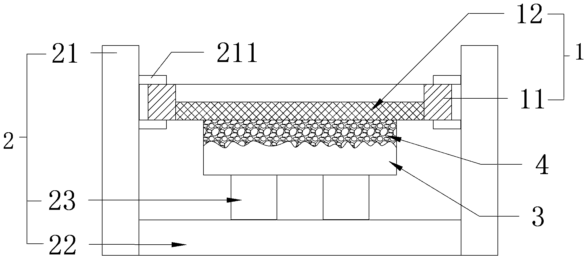
[0025] Please refer to figure 1 , the device for applying thermally conductive paste or conductive paste provided by the present invention includes a control surface device 1 and a positioning device 2 .

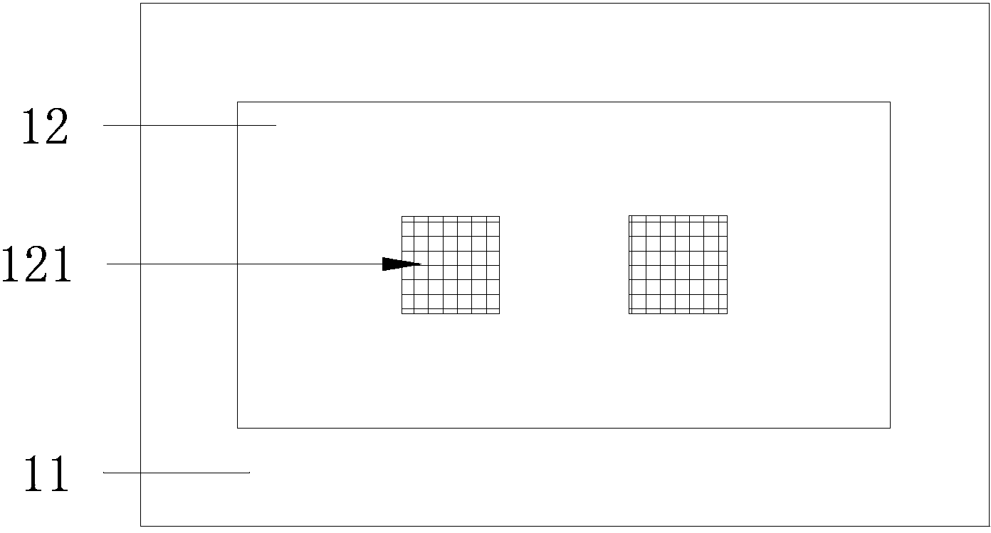
[0026] The control surface device 1 includes a mesh surface 12 and a screen frame 11; the mesh surface 12 is made of vertically and horizontally interwoven polyester filaments, which is the main area for paste application; the mesh frame 11 surrounds the mesh surface 12 Four weeks, for fixing and leveling the mesh surface 12.

[0027] The positioning device 2 includes a positioning frame 21 for fixing the control surface device 1, a positioning plate 22 positioned at the bottom of the positioning frame 21, and a positioning plate 22 arranged on the positioning plate 22 for fixing the object 3 to be plastered. Block 23. The contro...


PUM


Abstract

The invention discloses a thermally or electrically conductive paste smearing device and a smearing method. The device comprises a control surface device and a positioning device. The control surface device comprises a mesh surface with a smearing pattern, and a mesh frame fixing the mesh surface. The positioning device comprises a positioning rack used for fixing the control surface device on the positioning device, a positioning plate arranged on the bottom of the positioning rack, and a positioning block arranged on the positioning plate and used for fixing an object to be smeared. The invention also discloses a thermally or electrically conductive paste smearing method adopting the smearing device. The object to be smeared is fixed in the smearing device and is positioned under the mesh surface; a proper amount of the thermally or electrically conductive paste is arranged on the mesh surface; and the paste is evened by smearing. With the smearing device and method provided by the invention, paste levelness, uniformity, thickness, and smearing area can be controlled, such that electronic device conductivity can be ensured, and product reliability and consistency can be improved.

Description

technical field [0001] The invention relates to a tooling for electronic equipment, in particular to a device and method for applying heat-conducting paste or conductive paste. Background technique [0002] At present, heat conduction paste or conductive paste is usually used between the conductive sheets of electronic equipment to conduct heat or electricity conduction. The conductivity of electronic equipment plays a vital role in the performance of the equipment. It is uneven. The so-called surface contact is actually only a few points of contact. In this way, the total contact area is relatively small, and the conduction efficiency is relatively low, which limits the performance of electronic equipment. Especially like power amplifier equipment, it has extremely high requirements on signal or heat conduction performance, and the contact of several points may cause intermittent signal or even no signal. In terms of heat conduction, if the conduction is poor, it may cause...

Claims


Application Information

Patent Timeline
Patent Type & Authority Applications(China)
IPC IPC(8): B05C13/02B05C11/02
Inventor 郭然
Owner COMBA TELECOM SYST CHINA LTD
Why Eureka
Try Eureka