

Chain cutting device
A technology of cutting chain and chain shaft, applied in the field of chain cutting device, can solve the problems of inability to adapt to the chain, increase the cost of tools, poor generality, etc., achieve good social and economic benefits, and increase the effect of compatibility
- Summary
- Abstract
- Description
- Claims
- Application Information
AI Technical Summary
Problems solved by technology
Method used
Image

Examples
Embodiment Construction
[0015] Further description will be given below in conjunction with the accompanying drawings
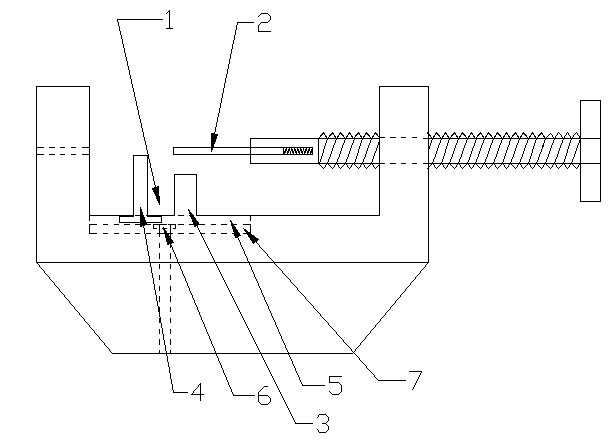
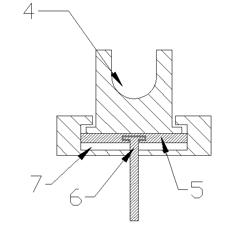
[0016] like Figure 1~2 As shown, a chain cutter includes a chain clipping slot 1, a chain cutter support, and a chain cutting push rod 62. The clipping slot 1 is composed of a chain shaft clip slot 4 and a limit block 3, and is characterized in that : the support of the chain cutter is processed with a groove parallel to the axis of the chain cutting push rod 62, the bottom of the chain shaft clamping groove 4 and the limit block 3 are embedded in the groove, and can be inserted along the groove move;
[0017] As a further innovation of the present invention, the groove is a T-shaped groove 7, and the bottom of the chain shaft clamping groove 4 and the limit stopper 3 is provided with a T-shaped buckle, and the chain shaft clamping groove 4 and the limit stopper 3 snap into the T-shaped slot 7 through the T-shaped buckle;
[0018] As a further innovation of the present invention,...
PUM
 Abstract
Description
Claims
Application Information