Test tube labeling machine

A labeling machine and test tube technology, applied in the field of labeling devices, can solve problems such as difficulty in maintaining barcode consistency, unsightly barcode stickers, and cumbersomeness, and achieve the effects of high practicability, convenient and efficient operation, and improved efficiency.

Inactive Publication Date: 2013-11-27
JILIN UNIV
View PDF4 Cites 6 Cited by
  • Summary
  • Abstract
  • Description
  • Claims
  • Application Information

AI Technical Summary

Problems solved by technology

[0003] Although there are many kinds of barcode printers on the market, the labels must be manually torn off from the supporting paper and then pasted on the product. Maintain Barcode Consistency

Method used


Image

  • Test tube labeling machine
  • Test tube labeling machine
  • Test tube labeling machine

Examples


Embodiment Construction

[0032] The present invention is described in detail below in conjunction with accompanying drawing:

[0033] The test tube labeling machine of the present invention is a supporting device of a barcode printer, and its purpose is to solve the problem that the barcode printer cannot directly label.

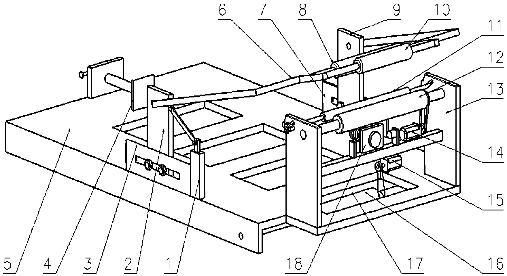
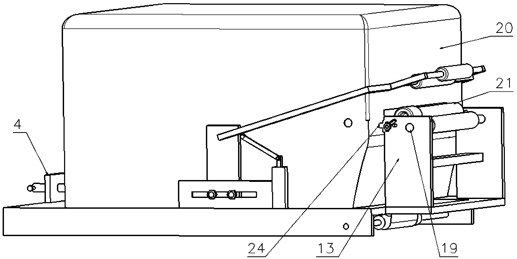
[0034] A test tube labeling machine is mainly composed of a pressure roller mechanism, a main and auxiliary roller mechanism, a clamping device 4 and a laser anti-loosening device 18; Roller support plate 2, No. 2 pressure roller support plate 9, pressure roller bracket 6, pressure roller 8, grip roller 10, No. 1 chute plate 3, No. 2 chute plate 7, travel switch 1;

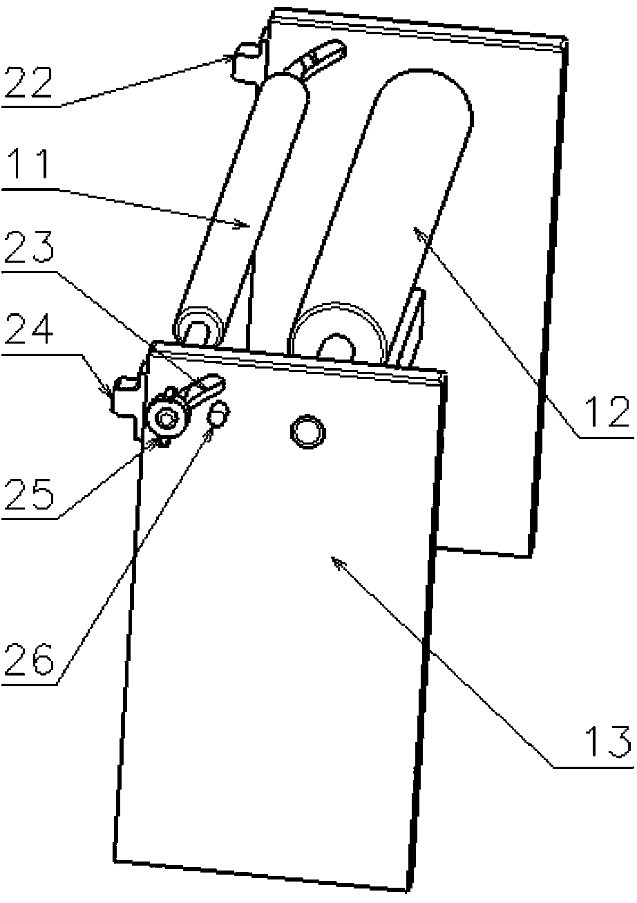
[0035] The main and auxiliary roller mechanism is made up of main roller 12, auxiliary roller 11, main roller motor 14, rotary shaft 16, rotary shaft motor 15.

[0036] refer to figure 1 and figure 2, the two chute plates of the pressure roller mechanism, No. 1 chute plate 3 and No. 2 chute plate 7 are symmetrically...


PUM


Abstract

The invention discloses a test tube labeling machine aiming to overcome the problem of hand labor. The test tube labeling machine mainly comprises a compression roller mechanism, a main-auxiliary roller mechanism, a clamping device and a laser locking device, wherein the compression roller mechanism mainly comprises a compression roller bracket which is arranged on a compression roller support plate I and a compression roller support plate II, a compression roller and a holding roller which are arranged on the compression roller bracket through bearings, a sliding groove plate I and a sliding groove plate II which are connected with the compression roller support plate I and the compression roller support plate II respectively in a sliding manner, and a travel switch which is fixed on a bottom plate and is in contact with the tail end of the compression roller bracket; the main-auxiliary roller mechanism mainly comprises a main roller, an auxiliary roller and a main roller motor, which are arranged at the front part of the bottom plate through a rack, a rotary shaft which is arranged under the bottom plate through a bearing, and a rotary shaft motor which is connected with the rotary shaft through belt transmission. The test tube labeling machine disclosed by the invention is capable of being matched with multiple bar code printers and labeling products of different diameters, and is simple in structure, convenient to debug and high in labeling efficiency.

Description

technical field [0001] The present invention relates to a labeling device, more specifically, the present invention relates to a test tube labeling machine. Background technique [0002] At present, there are many kinds of labeling machines, which are widely used in pharmaceutical industry, daily chemical industry, food industry, beverage industry, electronics and battery industry, petrochemical industry and medical industry, etc. It is an ideal equipment for high-precision and accurate labeling on small-sized materials such as circuit boards, automotive precision parts, cartons, magazines, mobile phone batteries, medicines, and daily chemicals, making product labels more beautiful. [0003] Although there are many kinds of barcode printers on the market, the labels must be manually torn off from the supporting paper and then pasted on the product. Maintain barcode consistency. Contents of the invention [0004] The problem to be solved by the present invention is to ove...

Claims


Application Information

Patent Timeline
Patent Type & Authority Applications(China)
IPC IPC(8): B65C3/06B65C9/18
Inventor 呼咏李凌邹青梁宁呼延宜人
Owner JILIN UNIV
Why Eureka
Try Eureka