Reverse dragging device for construction of dragging large-span steel braced girder

A technology of dragging device and steel truss girder, applied in bridges, bridge construction, erection/assembly of bridges, etc., can solve the problem that the longitudinal stability of steel truss girder members is not easy to maintain, the traffic safety under the bridge is hidden, and the dragging and rectification are difficult. problems, to achieve the effect of smooth and smooth motion characteristics, shortening the dragging time, and quick and convenient installation and dismantling.

Active Publication Date: 2013-11-27
中交二公局第四工程有限公司
View PDF4 Cites 24 Cited by
  • Summary
  • Abstract
  • Description
  • Claims
  • Application Information

AI Technical Summary

Problems solved by technology

[0007] In order to solve the defects existing in the prior art, the present invention provides a reverse pulling device for dragging construction of large-span steel truss girders, which solves the complex internal force changes of steel truss girder members in traditional dragging co

Method used


Image

  • Reverse dragging device for construction of dragging large-span steel braced girder
  • Reverse dragging device for construction of dragging large-span steel braced girder
  • Reverse dragging device for construction of dragging large-span steel braced girder

Examples


Example Embodiment

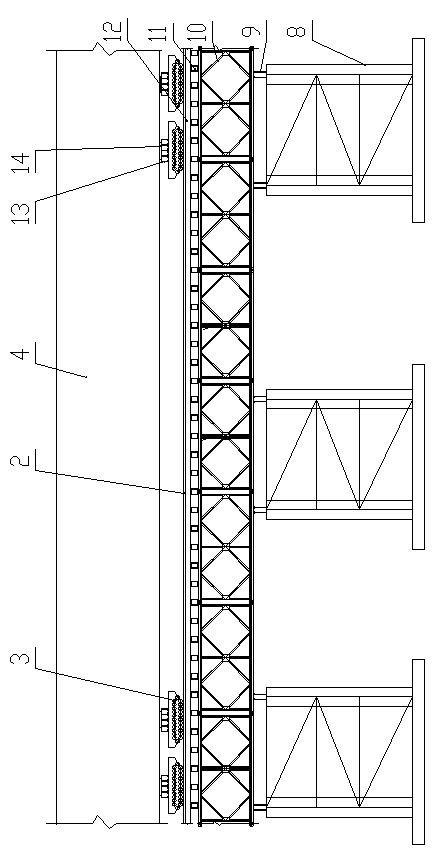
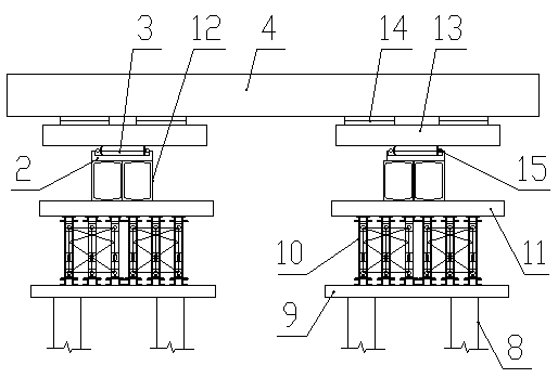
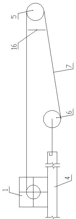
[0061] Such as figure 1 , figure 2 , image 3 with Figure 4 As shown, the reverse pulling device used for the pulling construction of large-span steel truss beams includes a temporary support and a hoist 1. The temporary support is provided with a slide 2 with a groove shape in cross section. The crawler conveyor 3 moves along the road 2, the steel truss beam 4 is set on the crawler conveyor 3, the hoist 1 is set on the steel truss beam 4, the upper part of the temporary support is provided with a fixed pulley block 5, and the winch 1 is wound The traction rope 7 bypasses the fixed pulley block 5 and is connected to the front end of the steel truss beam 4 through a movable pulley block 6.

[0062] The temporary support includes the steel pipe column 8, the I-steel distribution beam 9, the Bailey beam 10, the profiled steel sleeper 11 and the drag rail beam 12 arranged from bottom to top. The slide 2 is set on the drag rail beam 12, and the fixed pulley block 5 is set on Bere b...


PUM


Abstract

The invention discloses a reverse dragging device for construction of dragging a large-span steel braced girder. The reverse dragging device comprises a temporary support and a winch, wherein the temporary support is provided with a slide way with a groove-shaped cross section, a crawler-type conveyor capable of sliding along the slide way is arranged in the slide way, the steel braced girder is arranged on the crawler-type conveyor, the upper portion of the front end of the temporary support is provided with a fixed pulley block, and a hauling cable wound on the winch bypasses the fixed pulley block and is connected with the front end of the steel braced girder via a movable pulley block. The reverse dragging device for the construction of dragging the large-span steel braced girder is simple in structure, reasonable in design, good in bearing performance, safe, reliable, high in construction efficiency, high in practicability and worthy of popularization and application.

Description

technical field [0001] The invention belongs to the technical field of bridge engineering, and in particular relates to a reverse pulling device for dragging construction of large-span steel truss girders. Background technique [0002] The steel truss girder dragging method construction is to assemble the steel truss girders on the embankment at the bridge head or on the scaffolding, and set up a slideway on the steel truss girders, set a glideway on the embankment or scaffolding, and pass through the rollers between the upper and lower girders. Drag the steel truss girder to the predetermined bridge hole, and drop the girder into place. The drag method construction has the obvious advantage of less interference to the traffic under the bridge, and is a common method for the construction of steel truss beams spanning existing railway and highway business lines. [0003] The slideway and the drag system are important stress-bearing structures in the dragging construction. Wh...

Claims


Application Information

Patent Timeline
IPC IPC(8): E01D21/00
Inventor 潘建勤刘宏伟王豪吴洪群王建功廉则哲杨巍
Owner 中交二公局第四工程有限公司
Why Eureka
Try Eureka