[0031] In order to make the object, technical solution and advantages of the present invention clearer, the present invention will be further described in detail below in conjunction with the accompanying drawings and embodiments. It should be understood that the specific embodiments described here are only used to explain the present invention, not to limit the present invention.
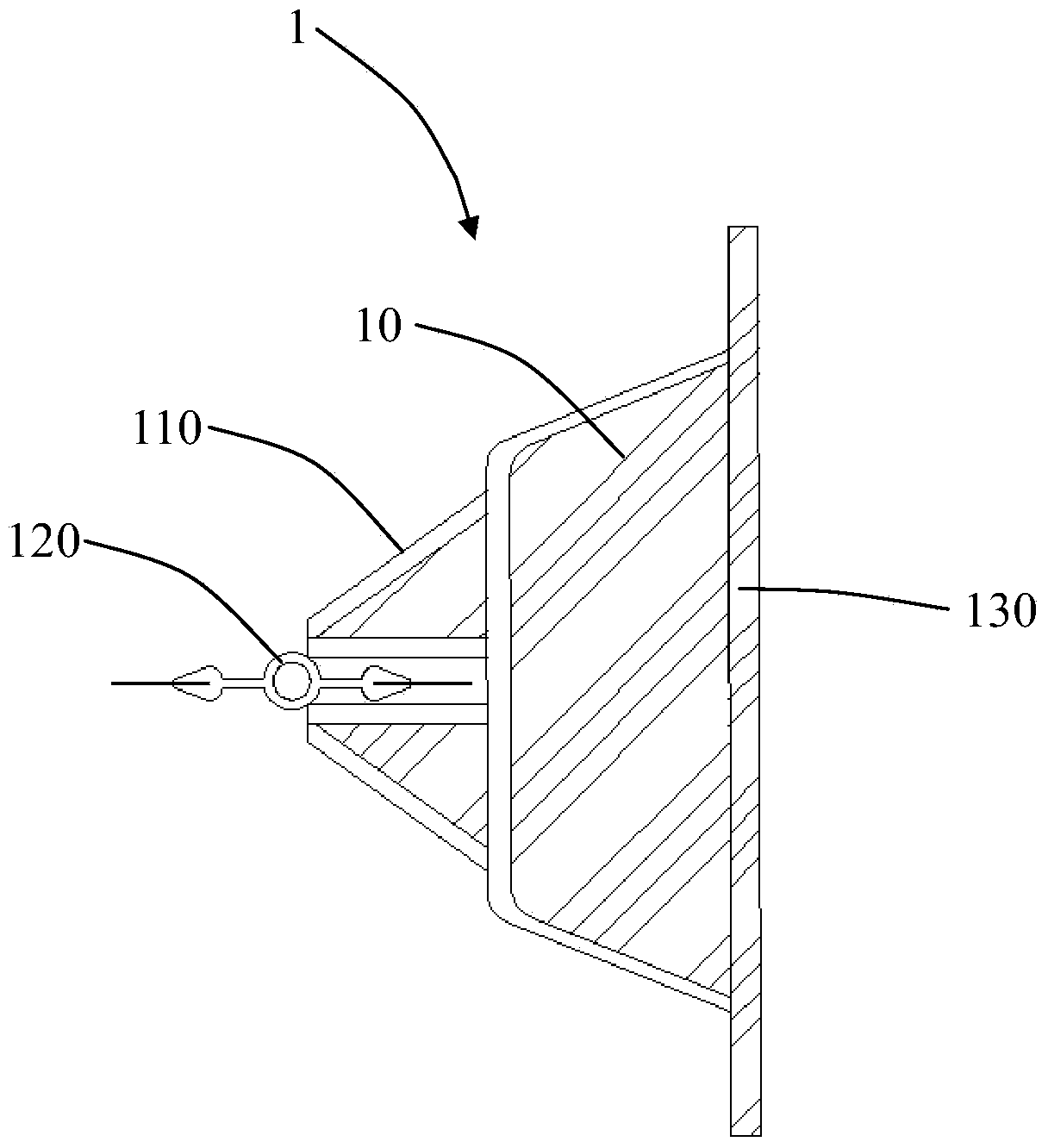
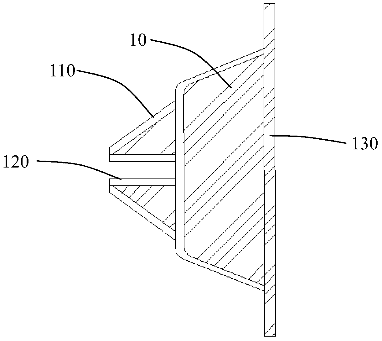
[0032] Cooperate with reference Figure 1 to Figure 4 As shown, the GXJ underground diaphragm wall rubber waterproof joint tool 1 of the present invention is used to connect the front section construction groove section 2 and the rear section construction groove section 3 of the underground diaphragm wall, including:
[0033] A joint box 10, the end of the joint box 10 close to the front construction tank section 2 forms an end surface with a continuous turning curve 110 along the width direction of the tank section, and the end near the front construction tank section 2 along the A groove 120 is further formed in the length direction of the slot section, and a partition plate 130 is fixedly connected to the end of the joint box 10 close to the construction slot section 3 of the rear section, and the width of the partition panel 130 is smaller than the width of the construction slot section 2 of the front section. .
[0034] A rubber water-isolation belt 20 , the first end of the rubber water-isolation belt 20 is embedded in the groove 120 , and the second end of the rubber water-isolation belt 20 is exposed outside the groove 120 . Both ends of the rubber water-isolation belt 20 are respectively embedded with a thin steel plate 210 .
[0035] Cooperate with reference Figure 4 to Figure 9 As shown, the underground diaphragm wall construction method using the GXJ underground diaphragm wall rubber water-proof joint tool 1 includes the following steps:
[0036] (1) combine Figure 4 As shown, through the Image 6 The trough-forming equipment 30 shown in the excavation of the front section construction slot section 2, place a joint tool 1 at the end of the front section construction slot section 2 close to the unexcavated back section construction slot section 3;
[0037] Among them, the trough forming equipment 30 with high vertical precision is selected for the excavation of the trough. The shape of the grab excavation bucket should be rectangular. During the whole process of trough formation, continuous monitoring and deviation correction are used to ensure the accuracy of the trench formation of the underground diaphragm wall.
[0038] (2) combine Figure 5 As shown, after clearing the holes and changing the grout, put the reinforcement cage 40 in the construction tank section 2 of the front section, and pour concrete;
[0039] (3) After the concrete in the construction groove section 2 of the front section is solidified, excavate the construction groove section 3 of the rear section;
[0040] (4) combine Image 6 , Figure 7 As shown, after clearing the hole, take out the joint box 10 of the joint tool 1 to form a joint 50 with a continuous turning curve 110, and the second end of the rubber water-proof belt 20 is buried in the completed front construction groove section 2 in the concrete;
[0041] Wherein, the grooving device 30 is respectively provided with buckle ears 31 corresponding to the two ends of the partition plate 130 , and the grooving device 30 fastens the partition plate 130 through the buckle ears 31 to take out the joint box 10 of the joint tool 1 .
[0042] (5) combine Figure 8 As shown, a joint tool 1 is placed near the end of the adjacent groove section 4 that has not yet been excavated in the construction groove section 3 of the rear section;
[0043] (6) After clearing the holes and changing the grout, put the reinforcement cage 40 in the construction tank section 3 of the rear section, and pour concrete to connect with the completed concrete of the construction tank section 2 of the front section;
[0044] (7) combine Figure 9 As shown, after the concrete of the construction tank section 3 in the back section is solidified, the first end of the rubber water-resisting belt 20 is embedded in the concrete section, and the connection with the concrete in the construction tank section 2 of the front section is completed;
[0045] (8) Excavate the adjacent groove section 4, and after clearing the hole, take out the joint box 10 of the joint tool 1, and repeat steps (5) to (7) until the construction of the entire underground diaphragm wall is completed.
[0046] In this construction method, after the construction of the front section construction slot section 2 is completed, without moving or pulling up the joint box 10, continue to excavate the back section construction slot section 3 adjacent to the front section construction slot section 2 with the trough forming equipment 30, so that the slots are formed When the equipment 30 grabs the soil, it will not collide with the joints that have been formed, which will affect the quality of the concrete in the completed front construction groove section 2 .
[0047] After the excavation of the construction tank section 3 in the rear section is completed, the joint box 10 is taken out from the concrete of the completed front section construction tank section 2, and after the joint box 10 is taken out, one end of the rubber water-resisting belt 20 is fixed on the completed front section In the concrete of the construction groove section 2, the other end exposed outside is fixed in when the concrete of the construction groove section 3 in the latter section is poured, so as to realize the function of water-proof sealing and form a joint with a water-stop effect.
[0048] Furthermore, the joint box 10 of the joint tool 1 has sufficient rigidity to ensure that it will not be deformed and damaged during being taken out, and the continuous turning curve 110 formed by its shape can extend the seepage path of water and play a better waterproof role. The length of the joint box 10 is the same as the depth of the underground diaphragm wall, and a section is arranged every 15 meters, and each section is connected with bolts and pins. The width of the partition plate 130 of the joint box 10 is 30mm smaller than the thickness of the underground continuous wall, which is convenient for buckling the buckle ears 31 on the groove forming equipment 30 .
[0049] The rubber water-proof belt 20 is temporarily fixed on the joint box 10 by using a wooden wedge, wherein the thickness of the thin steel plate 210 is 0.8mm, and the embedded depth is 30mm, which can ensure that the rubber water-proof belt 20 will not be damaged when the joint box 10 is taken out. It can also ensure that after the joint box 10 is taken out, the rubber water-proof belt 20 is firmly anchored to the completed concrete wall, thereby greatly increasing the waterproof effect of the joint.
[0050] For the convenience of taking out the joint box 10, jacking holes can also be set on the joint box 10, and after the concrete pouring is completed, the joint box 10 is jacked loose with a jack and then laterally taken out.
[0051] The above descriptions are only preferred embodiments of the present invention, and do not limit the present invention in any form. Although the present invention has been disclosed as above with preferred embodiments, it is not intended to limit the present invention. Anyone familiar with this professional technology Personnel, without departing from the scope of the technical solution of the present invention, when the technical content disclosed above can be used to make some changes or modifications to equivalent embodiments with equivalent changes, but all the content that does not depart from the technical solution of the present invention, according to the present invention Any simple modifications, equivalent changes and modifications made to the above embodiments by the technical essence still belong to the scope of the technical solution of the present invention.